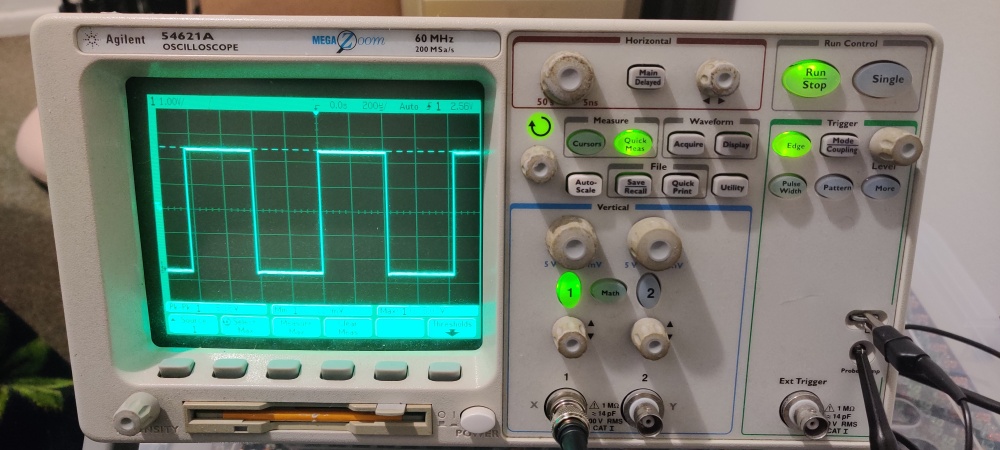
Recently I acquired an older Agilent 54621A oscilloscope for my at-home workstation, and yes, that is a floppy drive on the front.
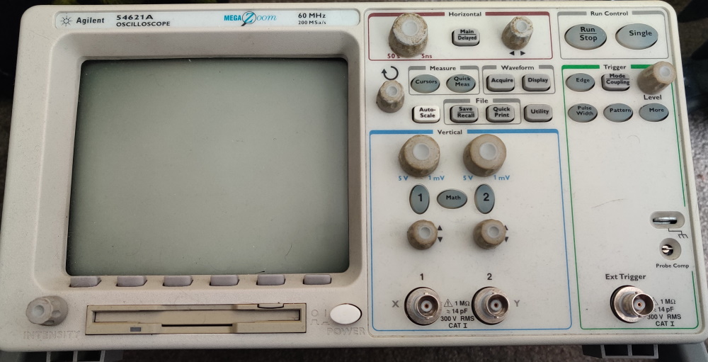
According to the person I got it from, the floppy drive still works, and they successfully used it to load data captures to their PC as recently as last year (2019). Bit old fashioned, but I suppose it’s servicable, given that I do own a USB floppy drive…
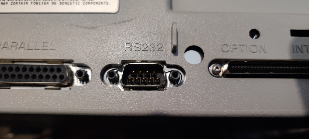
However, while I was looking it over, I noted the presence of an RS232 port:
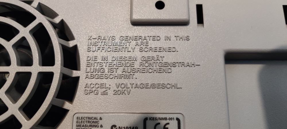
(I also noted this ominous warning message)
The presence of the RS232 got me thinking - Having never owned an Agilent oscilloscope before, I wonder what sort of data can be sent and recieved via this port?
Armed with google, I soon found this, the User’s guide for my oscilloscope, which mentions that software called BenchLinkXL 54600 software can be used to communicate with the oscilloscope! Success! I downloaded the software, but — turns out it’s not going to be quite that easy. It’s too old, and it won’t install nor work on Windows 10, nor on Wine under Ubuntu.
Still, the presence of this program implies that data must be able to go in and out of this port. I did more googling, and found this, the “Agilent InfiniiVision 5000 Series Oscilloscopes Programmer’s Guide”, an 884 page behemoth that, among other things, provides intricate details of an Agilent programming language to be used via a different set of custom software, the “Agilent IO Libraries Suite”.
But, my oscilloscope isn’t a 5000 series InfiniiVision, and the manual describes connecting the software via either LAN, USB, or GPIB, none of which I have present. I have only the RS-232 port, and the manual does not describe this at all as a connection option. Yet, one paragraph caught my eye, on page 36, which said The command set [in this manual] is similar to the 6000 Series oscilloscopes (and the *54620/54640 Series oscilloscopes* before them).
How interesting! That implies there is a programmer’s guide for my oscilloscope as well… So with another google search, I found this backed up on an mit.edu domain (thanks MIT), which is indeed the older programmer’s guide for my specific oscilloscope!
Now we’re in business. This manual specifically discusses talking to the RS232 port - in fact, it has an entire chapter devoted to it.
Linking the machines
The manual’s first step in getting an oscilloscope talking to a computer via RS232, is, as expected, configuring both machines settings so that they can understand one another. If you aren’t already familiar with how RS232 works, this is an important step. Unlike with newer protocols such as USB, RS232 devices need to be configured manually to speak with the same settings, i.e. speed, handshaking, parity checking, and so forth. If you don’t get these settings equivalent on both devices, then despite the fact that both devices speak the same language, they won’t be able to understand one another. From a metaphorical point of view, you might consider it as getting two language speakers to use the same dialect (e.g. american english vs british english) except more severe.
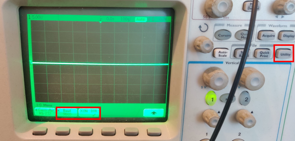
In order to configure the RS232 port on the oscilloscope, we just need to jump through a few on-screen menus, via Utility (Physical button) > I/O (on-screen button)
You can see we have only a couple of options, namely the baud rate and the handshaking method.
In the original user manual (the first document I linked), on page 6-8, these two options are explained thus:
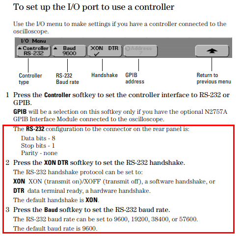
Given this information, we can now use any suitable tool to match these settings and try talk to the oscilloscope!
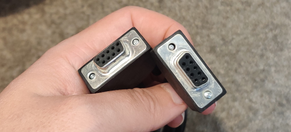
First things first - we need to actually connect the machines together. I own a USB to Serial cable, and it outputs the male side of the RS232. Annoyingly, the oscilloscope also has a male RS232 connector, so I need a female-to-female cable such as this one:
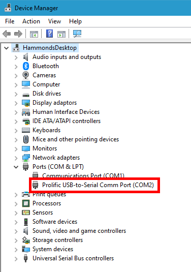
Now, after connecting all these together, we need to find what our computer has called this port. On Windows, you can find the COM port number using device manager:
On Linux/Ubuntu, I can find it in the terminal using dmesg | grep tty:

Let’s now pick a suitable tool and try and talk to the scope!
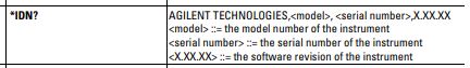
First we need to decide what to say. The programmer’s guide, from page 8-5 onwards, lists all available commands and queries. This one, *IDN?, seems to be a nice place to start:
The manual notes on page 5-8 that
the quoted string is placed on the command bus followed by a carriage return and linefeed (CRLF)”,
but also notes on page 1-13 that
The program instructions within a data message are executed after the program message terminator is received. The terminator may be either an NL (New Line) character, an EOI (End-Or-Identify) asserted in the GPIB interface, or a combination of the two. … The NL character is an ASCII linefeed (decimal 10)”.
It sounds like we could use either \r\n or just \n. I’ll use \n.
We now have everything we need to try and talk to the scope. Any tool should do - we could try using PuTTY (Windows) or minicom (Ubuntu), but actually I’m going to use Python3 using the pyserial library and just leap straight in to it.
New file, agilent-rs232.py:
import serial
# Open serial port using the DTR hardware handshaking mode and 9600 baud
# If I was on windows, according to my earlier screenshot I would use COM2
# All other pyserial defaults match the oscilloscope (8 data bits, 1 stop bit, no parity)
# A timeout is useful when deciding if a response is "finished"
ser = serial.Serial('/dev/ttyUSB0', 9600, dsrdtr=True, timeout=1)

# Let's try get a response from the IDN command
# The manual says all queries and responses should be terminated by a \n
ser.write(b'*IDN?\n')
ser.flush() #flush the serial to ensure the write is sent

#let's get the response
result = ser.readline() #read the response to the newline character

#print the result
print(result)

#be a tidy kiwi, don't forget to close your port
ser.close()
And let’s now try execute this:

Absolutely brilliant! We’re officially talking!
Note: I found that depending on the state of the program inside the oscilloscope, sometimes the first command I sent would fail. This was probably because I was doing a lot of experimentation and kept leaving it hanging, as it were. If it becomes an issue for you, you can try sending a \n before you send anything else.
A program to read the screen
Simply getting the identity of an oscilloscope is not tremendously interesting. What I really want here is to be able to read out the data the oscilloscope is currently seeing, so that I can analyse waveform data with my computer.
The programmer’s guide is actually really helpful here. It seems that anything you can do on the oscilloscope with buttons, you can also do via command queries.
I’m not actually so interested in that (for the purposes of this tutorial), since in general it is likely to be quicker to set up any captures I want to do using the physical buttons on the machine.
However, should you want to automate a process - for instance, if performing a common test set up - then the ability to do this would no doubt be useful.
No doubt this would have been one of the big selling points of the now-defunct BenchLinkXL software.
For now though, let’s just look at how we might extract captured data. The manual features this quote on page iii:
Using the :WAVeform commands, you can transfer the data to your controller. You may want to display the data, compare it to a known good measurement, or simply check logic patterns at various time intervals in the acquisition.
That sounds like exactly what I want to do. Here’s the specification of the WAVeform commands:
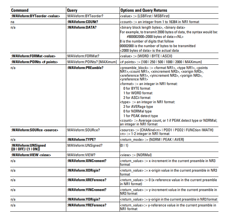
OK! Let’s use some of these commands as detailed. To make sure we’re capturing something, I’m going to attach the scope’s Channel 1 to the scope’s test port and set it using AUTOSCALE.
The first command I’m interested in is the :WAVEform:FORMat command.
That seems to set up the format of our incoming data. Transmitting in ASCII could be good for debugging, but I expect the additional overhead isn’t worth it when reading in screenloads of data. That leaves BYTE or WORD. When examining the documentation, this “reading” works a little like a microcontroller’s ADC - we’re essentially choosing the resolution of our returned data. Given that, I’m going to go with WORD format, so that we get 16 bits of resolution.
Given this is two bytes per value, we now need to choose what order we want to receive them in - I’ll go with “most significant byte” MSB first, since that makes logical sense to me (if it was base 10, and we were transmitting the number twenty-three, MSB first means we receive the 2 and then the 3 in that order).
Finally it appears we need to choose if we want signed or unsigned numbers. This doesn’t make a big difference to me, so I went with the default (signed).
We’ll also need to choose how many data points we want - I’ve gone with 1000, as it seems like a nice round number.
(Adding to agilent-rs232.py):
# ask for data to be formatted as signed WORDs (16 bits, so -32,768 through 32,767)
ser.write(b':WAVEform:FORMat WORD\n')
ser.write(b':WAVeform:BYTeorder MSBFirst\n')
ser.write(b':WAVeform:UNSigned 0\n')

# ask for 1000 data points
ser.write(b':WAVeform:POINts 1000\n')
ser.flush()
Hmm, this was an important step, but we didn’t actually ask the scope for any data! We’re almost there though. In order to understand any numbers we receive, we’re going to make sure we know what the oscilloscope is currently configured to capture. By this I mean we need to know what the oscilloscope’s scaling and offsets and references are set to.
Fortuately, these are also included in the :WAVeform command set. Let’s see if we can capture those parameters!
(Adding to agilent-rs232.py):
#set it to examine channel 1
ser.write(b':WAVeform:SOURce CHANnel1\n')

#let's now read what the oscilloscope is set to
ser.write(b':WAVeform:TYPE?\n')
ser.flush()
scope_read_type = ser.readline()[:-1] #TYPE? returns either NORM, PEAK, or AVER followed by a \n

#load dispay parameters. All of these return "NR3" format, which is a float-type, followed by a newline char
# X axis values are in seconds
# Y axis values are in volts
ser.write(b':WAVeform:XINCrement?\n')
ser.flush()
scope_x_increment = float(ser.readline())

ser.write(b':WAVeform:XORigin?\n')
ser.flush()
scope_x_origin = float(ser.readline())

ser.write(b':WAVeform:XREFerence?\n')
ser.flush()
scope_x_reference = float(ser.readline())

ser.write(b':WAVeform:YINCrement?\n')
ser.flush()
scope_y_increment = float(ser.readline())

ser.write(b':WAVeform:YORigin?\n')
ser.flush()
scope_y_origin = float(ser.readline())

ser.write(b':WAVeform:YREFerence?\n')
ser.flush()
scope_y_reference = float(ser.readline())

print("Oscilloscope mode: ",scope_read_type.decode())
print("X increment (S):", scope_x_increment)
print("X reference (S):", scope_x_reference)
print("X origin (S):", scope_x_origin)

print("Y increment (V):", scope_y_increment)
print("Y reference (V):", scope_y_reference)
print("Y origin (V):", scope_y_origin)
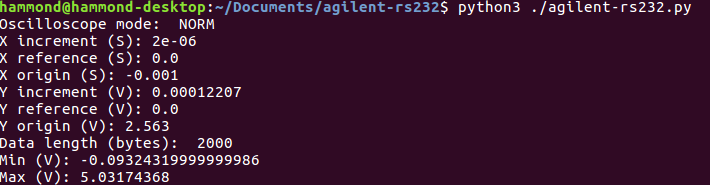
If I now run this, I get the following output:
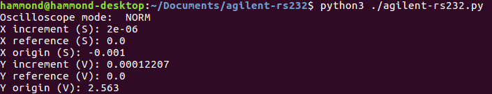
Brilliant! Let’s do a sanity check. The oscilloscope says that the scope_y_increment is 0.00012207. The manual says this is multiplied by returned values to get their voltage (before offsets and references). Thus, if we just multiply this by our range (remember we picked WORD as our format, so we have 2^16 values) we’ll get the range of voltages the oscilloscope could currently return. 0.00012207 x 2^16 is almost exactly 8V. Now, if we look back at the autoscale photo, we can see that the y scale is currently 1.00V, and there are 9 y ticks -> there’s a range of 8V on screen!
We can also do an x-range sanity check. The scope_x_increment is 2e-06, or 2 microseconds. On the scope itself it says that the display is configured with vertical ticks spaced at 200 microseconds, and there are 11 ticks, meaning there is a range of 2000 microseconds on screen.
Recall that we asked for 1000 data points - therefore, if they are spaced 2 microseconds apart, they will match the 2000 microseconds of on screen range!
Excellent. The only thing left to do now is to perform a capture! I changed the baud rate in python and the oscilloscope to 57600 to speed this up a bit.
Under the DATA? command it says that the data is formatted as preamble,data where preamble is made up of #[length of length of data][length of data].
The example they give is receiving 2000 bytes of data, the preamble will be formatted #800002000, where 8 is the length of 00002000 (i.e. 8 bytes) and 2000 is the length of the data (i.e. 2000 bytes).
So, let’s add a bit of code to agilent-rs232.py:
# let's now try get the data!
ser.write(b':WAVeform:DATA?\n')
ser.flush()
scope_data_bytes = ser.readline() #the response here is formated preamble,data where the preamble provides the length of the data

#the preamble is in the format #[length of length of data][length of data],[data]
scope_data_preamble_len = scope_data_bytes[1] - 48 #convert the ASCII digit to an integer
scope_data_len = int(scope_data_bytes[2:2+scope_data_preamble_len]) #the data length in bytes
print("Data length (bytes): ", scope_data_len)
And testing:
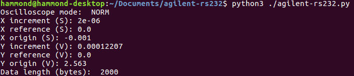
Perfect, with our current settings, 1000 data points will indeed be 2000 bytes long.
Finally, we want to convert those incoming data points into voltages at times.
This is going to look a little involved, mainly because the raw data is just a long stream of bytes stored in scope_data_bytes.
- Find the two bytes representing a sample point
- Convert the two bytes into the integer format in python
- Convert the integer into a voltage using the formula specified in the manual, that is,
voltage = [(data value - yreference) * yincrement] + yorigin - Store the voltage in a list
As a sanity check, we’ll quickly check the maximum and minimum voltage we captured:
And so (continuing agilent-rs232.py):
data_points = []
for i in range(0, scope_data_len, 2):
    data_offset = i+scope_data_preamble_len + 2
    data_point = int.from_bytes(scope_data_bytes[data_offset:data_offset+2], byteorder='big', signed=True)

    #using the formula from the agilent 5000 series programmer's guide reference manual page 595
    # voltage = [(data value - yreference) * yincrement] + yorigin
    data_point_voltage = ((data_point - scope_y_reference) * scope_y_increment) + scope_y_origin
    data_points.append(data_point_voltage)

print("Min (V):", min(data_points))
print("Max (V):", max(data_points))
And output:
Brilliant! We’re almost ready to graph this. The last thing we need is to know when each of those data points are in time.
Fortunately, the manual also gives us a formula for this - time = [(data point number - xreference) * xincrement] + xorigin.
So we can write a bit more code (continuing agilent-rs232.py):
#work out the times
data_points_times = []
for i in range(0, len(data_points)):
    #using the formula from the agilent 5000 series programmer's guide reference manual page 595
    # time = [(data point number - xreference) * xincrement] + xorigin
    data_point_time = ((i - scope_x_reference) * scope_x_increment) + scope_x_origin
    data_points_times.append(data_point_time)
Now let’s have a go plotting (continuing agilent-rs232.py)!
#need to add this, best to add it at the top
import matplotlib.pyplot as plt

# . . .

#plot our results
plt.plot(data_points_times, data_points)
plt.title("Oscilloscope capture (mode: "+scope_read_type.decode()+")")
plt.xlabel("Time (S)")
plt.xticks(rotation=45)
plt.ylabel("Voltage (V)")
plt.tight_layout()
plt.show()
Our final output:
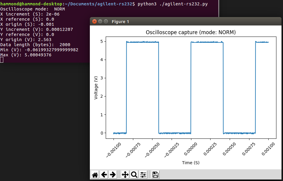
Absolutely outstanding!
Tidying the program
From here, it’s a small matter to make the python script a little tidier, add things like command line arguments and such. I did that too - if you’re interested, all the code is on the project github.
Can I use this?
Of course! Well, if you have an Agilent oscilloscope with an RS232 port, anyway! The source code is on the project github and released freely under the MIT license.
If you don’t have a compatible oscilloscope with what was made here, hopefully the idea I’ve outlined and the steps I’ve detailed are enough to get you started with a project that can achieve a similar goal with your own machine?