Embedded projects often call for some kind of data storage and retrieval. For instance, you might have need for a data logger to record data points over long periods of time. You might have user settings that need to be preserved after the device is shut off and rebooted. You might want to profile your application, or debug certain features.
There are a number of ways to do this, and one of my favourites is to add an SD (or other memory) card to a project. It’s not too complicated, and it adds a lot of flexibility, as you can easily take the SD card out of the project and examine it with another machine. My second favourite method is to slap on a 20 cent EEPROM, but while that’s cheaper it’s a lot less flexible and usually stores a lot less data!
I’ve been asked more than once if I have any good tutorial resources for adding SD cards to an embedded project. Well, there are a few good tutorials and resources floating around online (including even my own resource from 2017) but some of them are a bit dated, relying on older tools and libraries. Further, while there are some amazing resources (e.g. ChaN’s) on talking to SD cards over SPI, there are less that describe how to interface this with file systems such as FAT, and less again that describe how to do it while also working with STM32’s build environments. Complicating matters is that officially you should use the STM32 SDIO peripheral to interface with an SD card - however, not all STM32s have the SDIO peripheral, leaving us to fall back on the SPI method (That said, it is worth noting that not all SD cards support the SPI interface).
Well, in this tutorial I’m going to walk through the steps that one would use to get an SD card working over the SPI interface on a STM32 dev board (re-)using my FatFS driver from 2017. FatFS is an amazing open source project also provided by ChaN which has since been integrated into the STM32Cube tools. If you’re interfacing with an SD card using the SDIO peripheral, it’s pretty easy and the tooling does most of it for you. If you’re working with other kinds of configurations, e.g. SD card over SPI, it’s actually still pretty easy - you just need the appropriate driver! So, today I want to show how you can use the FatFS libraries within the STM32CubeIDE development environment, and show how you can simply drop in the appropriate SPI driver to make everything work.
I’ll be assuming that you already know the basics of creating a project and setting up debugging and so on. If not, then please check out this earlier tutorial, in which I walk through getting started with STM32CubeIDE.
TL;DR: CubeIDE with FatFS. The complete code project is available here.
Equipment for this tutorial
Today I will be using the following:
- (Free) Ubuntu Linux 20.04 because developing on Linux makes me happy and Ubuntu makes it easy. Don’t worry if you’re on Windows, you should be able to follow along with roughly the same steps.
- (Free) STM32CubeIDE
- ($19.95 from Amazon) The
Nucleo-F303REdevelopment board. - ($5 from Amazon) An SD card breakout board (comes in a pack of two).
- ($6 from Amazon) Easy-to-use ribbon cables (there’s more than you need here but they’re handy to have around).
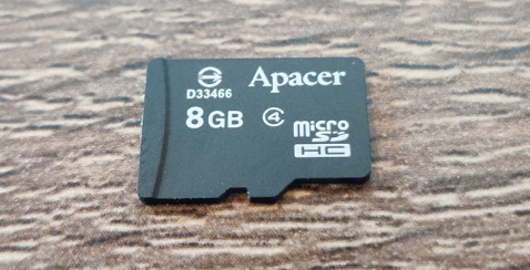
- A micro SD card - note that not all SD cards will work in SPI mode. I have an Apacer one that works, and a Kingston one that does not. YMMV.
Note: The above Amazon links are affiliate links. As always I encourage you to shop around, but Amazon usually has pretty good pricing.
The software stack
In this blog post I’m not terribly interested in the low-level behaviour we’re using to get an SD card working beyond “we talk to it over SPI”. It’s worth knowing though, so go check out what ChaN wrote, and then come back. The key knowledge that I want to show in this tutorial is around the architecture of an embedded application that wants to use an SD card with a FAT file system (using the FatFS library).
In general it’s always useful to visualise the architecture of what you are working with. In a FatFS system it looks like this:
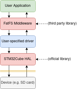
FatFS is provided as a Middleware which can translate FAT file structures in memory into their actual files. Handy! For it to do its magic, it needs access to a storage medium. It relies on several functions as ChaN notes here:
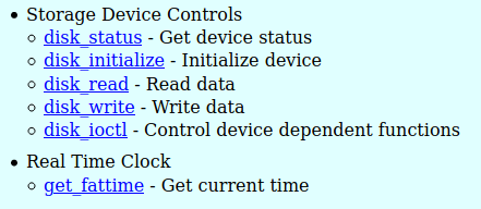
It’s these functions that we’ll need to provide. For an SD card they’re pretty involved, but don’t worry, we’ll just be dropping in a pre-existing driver and linking it up.
Setting up the Project and Pins
- Open STM32CubeIDE.
- Start a new project for the
Nucleo-F303REdev board (or w/e you’re using) called something sensible e.g. cubeide-sd-card. - Answer ‘Yes’ to Initialize all peripherals in their default configuration?.
- Answer ‘Yes’ to Open device configuration view?.
The Device Configuration View is where you configure exactly which pins/peripherals are enabled and what their settings are. Since we want to be connecting to an SD card, we need to enable an SPI port and then decide where to wire it.
Let’s quickly work out where our pins are going. Our goal here is to identify an SPI peripheral with easy-to-access pins as well as a GPIO pin to use as a chip select.
On the Nucleo-F303-RE we have both Arduino style headers as well as ST’s branded morpho headers, which are the double rows of pins down each side.
While it’s tempting to use the Arduino header’s SPI port (since it’s labelled on the silk screen) I actually don’t like to, as the on-board LED shares one of the pins (one of the worst features of this particular development kit).
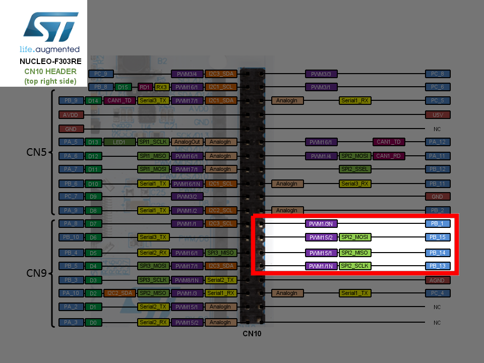
So, instead I will take a look at the morpho header pinouts.
This document from ST provides us with the correct pinout for the F303-RE, or alternatively (and in a more attractive and detailed way) the same info is presented on ST’s mbed OS website here.
Straight away I can see that SPI2 is the winner - it is broken out onto the pins in the bottom right, along with PB1 which we will use for the chip select line.
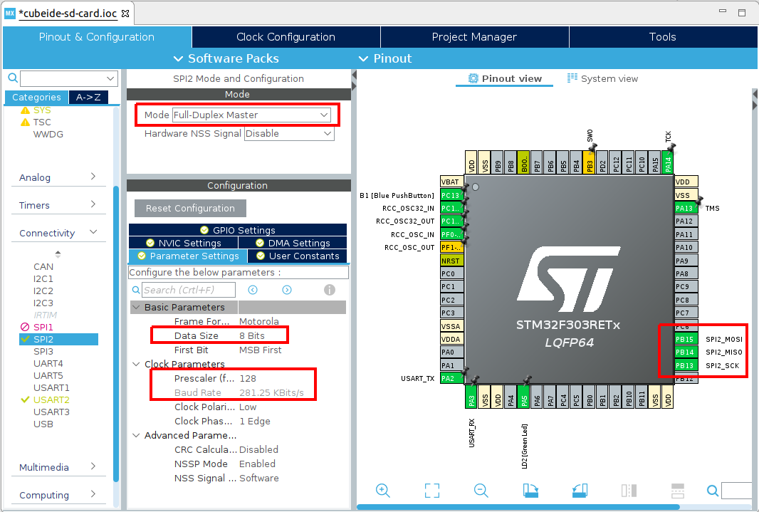
So, let’s set up our SPI2 and GPIO in the Device Configuration View. Click SPI2 on the left, and then set it to Full Duplex Master with no Hardware NSS. Then set the Data Size to 8 bits, and the clock prescaler to 128 (SD cards start up with low speeds and switch to higher speeds later. We’ll look at how to do this soon).
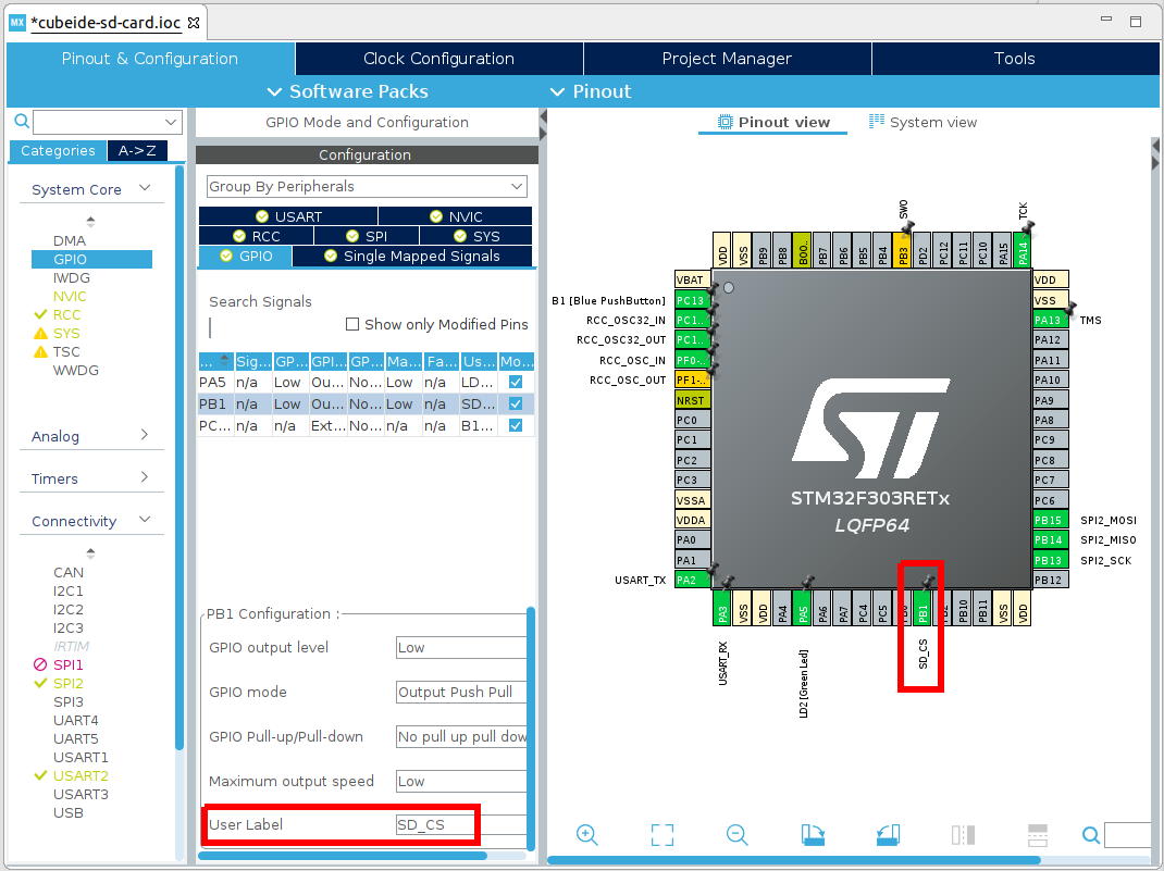
Then, create your Chip Select line on PB1 - I find setting a sensible name is also good:
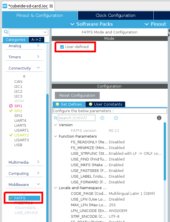
Finally, as we’re going to be using the SD card with the FAT file system, scroll down in the device categories to Middleware, and expand this, then enable FATFS as User-defined. You may leave all other parameters as their defaults.
Now save your Device Configuration, and when it asks, ‘Yes’ to Do you want to generate Code? and ‘Yes’ to Do you want to open [the C/C++] perspective now?.
Wiring the SD card adapter
Now that you have configured the pins in CubeIDE, we need to physically wire them in real life!
Using the SPI pins from the earlier figure, and the power pins depicted here,
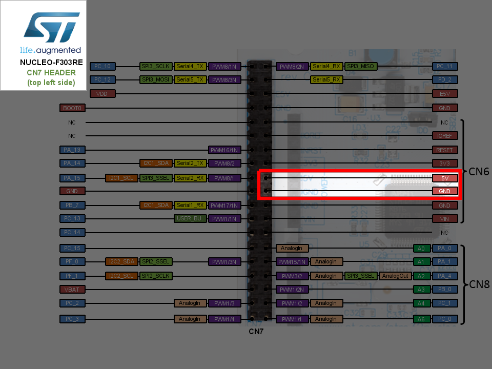
Use your ribbon cables and connect these to the appropriate pins on the SD card adapter module (the module’s pins are labelled on the silk screen, so this isn’t much of a chore).
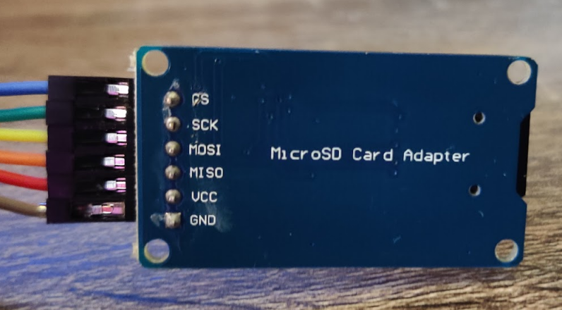
In table form, the connections are as follows:
| SD Adapter side | Nucleo-F303RE side |
|---|---|
| CS | PB1 (GPIO SD_CS) |
| SCK | PB13 (SPI2 SCLK) |
| MOSI | PB15 (SPI2 MOSI) |
| MISO | PB14 (SPI2 MISO) |
| VCC | 5V |
| GND | GND |
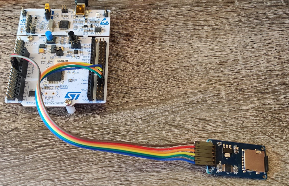
Once you’re finished it should look something like this:
Key files to make this work
It’s now time to put our driver in.
In 2017 I worked with some of ChaN’s source code to produce a driver compatible with the predecessor to CubeIDE, CubeMX.
This driver will work with CubeIDE, but I’ve made a few changes to update it (and make it better).
It has two files, user_diskio_spi.c which you can get here, and user_diskio_spi.h which you can get here.
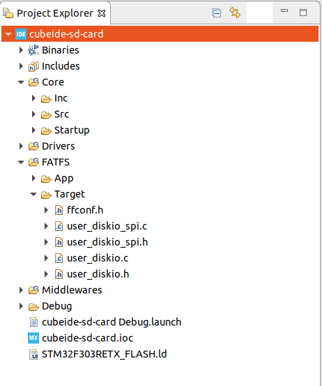
Download these and copy them into your FATFS/Target directory (you can also copy them into Core/Src and Core/Inc respectively if you’d prefer, but I think that’s messier).
When you’ve done this, your file viewer should now look something like this:
Now we need to link the driver into FatFS. This will involve just a simple change to the user_diskio.c file. There are more elegant ways to do this, but if we’re not careful we will fall afoul of the STM32CubeIDE code generator, so we are limited to changing code in the commented areas.
What we’re going to do is embed calls to the SPI driver functions in each of the autogenerated driver stubs.
I’ve annotated the changes below with //ADD THIS LINE. You’ll see that each of the function calls just calls the appropriate function in our driver.
In user_diskio.c Decl:
/* USER CODE BEGIN DECL */

/* Includes ------------------------------------------------------------------*/
#include <string.h>
#include "ff_gen_drv.h"
#include "user_diskio_spi.h"
In user_diskio.c Private Functions:
/* Private functions ---------------------------------------------------------*/

/**
  * @brief  Initializes a Drive
  * @param  pdrv: Physical drive number (0..)
  * @retval DSTATUS: Operation status
  */
DSTATUS USER_initialize (
	BYTE pdrv           /* Physical drive nmuber to identify the drive */
)
{
  /* USER CODE BEGIN INIT */
	return USER_SPI_initialize(pdrv); //ADD THIS LINE
  /* USER CODE END INIT */
}

/**
  * @brief  Gets Disk Status
  * @param  pdrv: Physical drive number (0..)
  * @retval DSTATUS: Operation status
  */
DSTATUS USER_status (
	BYTE pdrv       /* Physical drive number to identify the drive */
)
{
  /* USER CODE BEGIN STATUS */
	return USER_SPI_status(pdrv); //ADD THIS LINE
  /* USER CODE END STATUS */
}

/**
  * @brief  Reads Sector(s)
  * @param  pdrv: Physical drive number (0..)
  * @param  *buff: Data buffer to store read data
  * @param  sector: Sector address (LBA)
  * @param  count: Number of sectors to read (1..128)
  * @retval DRESULT: Operation result
  */
DRESULT USER_read (
	BYTE pdrv,      /* Physical drive nmuber to identify the drive */
	BYTE *buff,     /* Data buffer to store read data */
	DWORD sector,   /* Sector address in LBA */
	UINT count      /* Number of sectors to read */
)
{
  /* USER CODE BEGIN READ */
	return USER_SPI_read(pdrv, buff, sector, count); //ADD THIS LINE
  /* USER CODE END READ */
}

/**
  * @brief  Writes Sector(s)
  * @param  pdrv: Physical drive number (0..)
  * @param  *buff: Data to be written
  * @param  sector: Sector address (LBA)
  * @param  count: Number of sectors to write (1..128)
  * @retval DRESULT: Operation result
  */
#if _USE_WRITE == 1
DRESULT USER_write (
	BYTE pdrv,          /* Physical drive nmuber to identify the drive */
	const BYTE *buff,   /* Data to be written */
	DWORD sector,       /* Sector address in LBA */
	UINT count          /* Number of sectors to write */
)
{
  /* USER CODE BEGIN WRITE */
  /* USER CODE HERE */
	return USER_SPI_write(pdrv, buff, sector, count); //ADD THIS LINE
  /* USER CODE END WRITE */
}
#endif /* _USE_WRITE == 1 */

/**
  * @brief  I/O control operation
  * @param  pdrv: Physical drive number (0..)
  * @param  cmd: Control code
  * @param  *buff: Buffer to send/receive control data
  * @retval DRESULT: Operation result
  */
#if _USE_IOCTL == 1
DRESULT USER_ioctl (
	BYTE pdrv,      /* Physical drive nmuber (0..) */
	BYTE cmd,       /* Control code */
	void *buff      /* Buffer to send/receive control data */
)
{
  /* USER CODE BEGIN IOCTL */
	return USER_SPI_ioctl(pdrv, cmd, buff); //ADD THIS LINE
  /* USER CODE END IOCTL */
}
#endif /* _USE_IOCTL == 1 */
Finally, for our driver to work, we need to make just one more change - we need to tell it which SPI we are using!
You’ll notice at the top of user_diskio_spi.c the following snippet:
//Make sure you set #define SD_SPI_HANDLE as some hspix in main.h
//Make sure you set #define SD_CS_GPIO_Port as some GPIO port in main.h
//Make sure you set #define SD_CS_Pin as some GPIO pin in main.h
extern SPI_HandleTypeDef SD_SPI_HANDLE;
So this is what we need to do now. Pop over into main.h. You’ll see thanks to our Device configuration from earlier that SD_CS_GPIO_Port and SD_CS_Pin are already set for us, so we only need to add the following line:
in main.h Private defines:
/* USER CODE BEGIN Private defines */
#define SD_SPI_HANDLE hspi2
/* USER CODE END Private defines */
Finally, we need to consider the clock speeds for our SD card driver. If you’re using the Nucleo-F303RE, great, the defaults are what I was using.
If not, open up user_diskio_spi.c and just make sure these prescalar values work for you to generate approximately the listed speeds:
in user_diskio_spi.c:
//(Note that the _256 is used as a mask to clear the prescalar bits as it provides binary 111 in the correct position)

#define FCLK_SLOW() { MODIFY_REG(SD_SPI_HANDLE.Instance->CR1, SPI_BAUDRATEPRESCALER_256, SPI_BAUDRATEPRESCALER_128); }	/* Set SCLK = slow, approx 280 KBits/s*/
#define FCLK_FAST() { MODIFY_REG(SD_SPI_HANDLE.Instance->CR1, SPI_BAUDRATEPRESCALER_256, SPI_BAUDRATEPRESCALER_8); }	/* Set SCLK = fast, approx 4.5 MBits/s */
We’re ready to go!
Testing and correct output
First, ensure your micro SD card is formatted to the FAT file system (in your operating system of choice just insert the SD card and then format it to FAT32/FAT/msdos - not exFAT).
Then, create a file test.txt in the root of your SD card. Puyt something in it, e.g. Hello I'm on an SD card. Save the file and remove the SD card from your computer.
Now plug the SD card into the module, and connect the development kit to your PC. We’re going to make output will be coming via the integrated COM port, so make sure you open that up using either e.g. minicom (Ubuntu) or PuTTY (Windows).
Now let’s add some code to main.c. We’re going to want a printf that outputs to the integrated terminal, so we need to add a few things:
in main.c Private includes:
/* Private includes ----------------------------------------------------------*/
/* USER CODE BEGIN Includes */
#include <stdio.h>
#include <string.h>
#include <stdarg.h> //for va_list var arg functions
/* USER CODE END Includes */
in main.c Private function prototypes:
/* USER CODE BEGIN PFP */
void myprintf(const char *fmt, ...);
/* USER CODE END PFP */
in main.c User Code 0:
/* USER CODE BEGIN 0 */
void myprintf(const char *fmt, ...) {
  static char buffer[256];
  va_list args;
  va_start(args, fmt);
  vsnprintf(buffer, sizeof(buffer), fmt, args);
  va_end(args);

  int len = strlen(buffer);
  HAL_UART_Transmit(&huart2, (uint8_t*)buffer, len, -1);

}
/* USER CODE END 0 */
Great, that will let us call myprintf() as if it was any other printf with strings of up to 256 characters and the output will come out on UART2 (the virtual COM port).
Now let’s add some file system fun!
in main.c From User Code 2 to User Code 3 (inside the main() function):
  /* USER CODE BEGIN 2 */

  myprintf("\r\n~ SD card demo by kiwih ~\r\n\r\n");

  HAL_Delay(1000); //a short delay is important to let the SD card settle

  //some variables for FatFs
  FATFS FatFs; 	//Fatfs handle
  FIL fil; 		//File handle
  FRESULT fres; //Result after operations

  //Open the file system
  fres = f_mount(&FatFs, "", 1); //1=mount now
  if (fres != FR_OK) {
	myprintf("f_mount error (%i)\r\n", fres);
	while(1);
  }

  //Let's get some statistics from the SD card
  DWORD free_clusters, free_sectors, total_sectors;

  FATFS* getFreeFs;

  fres = f_getfree("", &free_clusters, &getFreeFs);
  if (fres != FR_OK) {
	myprintf("f_getfree error (%i)\r\n", fres);
	while(1);
  }

  //Formula comes from ChaN's documentation
  total_sectors = (getFreeFs->n_fatent - 2) * getFreeFs->csize;
  free_sectors = free_clusters * getFreeFs->csize;

  myprintf("SD card stats:\r\n%10lu KiB total drive space.\r\n%10lu KiB available.\r\n", total_sectors / 2, free_sectors / 2);

  //Now let's try to open file "test.txt"
  fres = f_open(&fil, "test.txt", FA_READ);
  if (fres != FR_OK) {
	myprintf("f_open error (%i)\r\n");
	while(1);
  }
  myprintf("I was able to open 'test.txt' for reading!\r\n");

  //Read 30 bytes from "test.txt" on the SD card
  BYTE readBuf[30];

  //We can either use f_read OR f_gets to get data out of files
  //f_gets is a wrapper on f_read that does some string formatting for us
  TCHAR* rres = f_gets((TCHAR*)readBuf, 30, &fil);
  if(rres != 0) {
	myprintf("Read string from 'test.txt' contents: %s\r\n", readBuf);
  } else {
	myprintf("f_gets error (%i)\r\n", fres);
  }

  //Be a tidy kiwi - don't forget to close your file!
  f_close(&fil);

  //Now let's try and write a file "write.txt"
  fres = f_open(&fil, "write.txt", FA_WRITE | FA_OPEN_ALWAYS | FA_CREATE_ALWAYS);
  if(fres == FR_OK) {
	myprintf("I was able to open 'write.txt' for writing\r\n");
  } else {
	myprintf("f_open error (%i)\r\n", fres);
  }

  //Copy in a string
  strncpy((char*)readBuf, "a new file is made!", 19);
  UINT bytesWrote;
  fres = f_write(&fil, readBuf, 19, &bytesWrote);
  if(fres == FR_OK) {
	myprintf("Wrote %i bytes to 'write.txt'!\r\n", bytesWrote);
  } else {
	myprintf("f_write error (%i)\r\n");
  }

  //Be a tidy kiwi - don't forget to close your file!
  f_close(&fil);

  //We're done, so de-mount the drive
  f_mount(NULL, "", 0);

  /* USER CODE END 2 */

  /* Infinite loop */
  /* USER CODE BEGIN WHILE */
  while (1)
  {
    /* USER CODE END WHILE */

    /* USER CODE BEGIN 3 */
      //Blink the LED every second
	  HAL_GPIO_TogglePin(LD2_GPIO_Port, LD2_Pin);
	  HAL_Delay(1000);
  }
  /* USER CODE END 3 */
Alright, you’re ready to go!
Compile and download the project to your microcontroller. In your terminal, you should see the following appear!
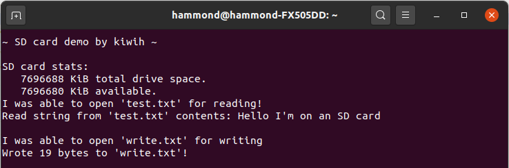
If so, great! If not, rats.
If any numerical errors are given you can convert them into their meaning from the look up table in Middlewares\Third_Party\FatFS\src\ff.h. You should double check your wiring as well. Sadly, not all SD cards will work over SPI - I wasted a good few hours with a Kingston SD card before changing to an Apacer one that just worked instantly. Good luck!
Also note that if you’re using this process with your own custom circuit, you may need pull-up resistors on the SCK, MISO, and MOSI lines. The SD card module I used in this post includes them internally - if you’re wiring your own design, you might find you need to add them. You can also consider enabling the internal pull up resistors. More details are included here.
If you would like the complete code that accompanies this blog post, it is made available in the associated Github repository here.