Measuring, monitoring, and reacting to the passage of time in embedded systems is an ubiquitous requirement.
For instance, you might decide that you want to toggle an output every millisecond.
You might be tasked to implement a system that samples an ADC once a second.
You might want to change your main()’s while(1) to feature a delay such that it becomes a loop with a fixed period.
In order to achieve this, you must become proficient with one of the most useful peripherals you’ll ever encounter within your microcontrollers: Timers. These are embedded counters which measure the passage of time as a function of counting microcontroller clock ticks (you can actually get them to count other things as well, for instance pulses on an external pin).
Setting up timers, however, can be a little tricky - especially in microcontrollers as capable as the STM32F series. So, in this, my third tutorial using STM32CubeIDE, I’m going to walk through a quick explanation of how we can get started with some of the most common use cases, and I’ll finish with a (very silly) demo application where we (ab)use a timer to produce an AM radio signal.
I’ll be assuming that you already know the basics of creating a project, navigating inside CubeIDE, and setting up debugging and so on. If not, then please check out this earlier tutorial, in which I walk through getting started with STM32CubeIDE.
So what are we waiting for? Let’s get started!
TL;DR: Timers. The complete code project is available here.
Equipment for this tutorial
Today I will be using the following:
- (Free) Ubuntu Linux 20.04 because developing on Linux makes me happy and Ubuntu makes it easy. Don’t worry if you’re on Windows, you should be able to follow along with roughly the same steps.
- (Free) STM32CubeIDE
- ($19.95 from Amazon) The
Nucleo-F303REdevelopment board. - ($6 from Amazon) Easy-to-use ribbon cables (there’s more than you need here but they’re handy to have around).
Note: The above Amazon links are affiliate links. As always I encourage you to shop around, but Amazon usually has pretty good pricing.
Setting up the Project
- Open STM32CubeIDE.
- Start a new project for the
Nucleo-F303REdev board (or w/e you’re using) called something sensible e.g. cubeide-timers-demo. - Answer ‘Yes’ to Initialize all peripherals in their default configuration?.
- Answer ‘Yes’ to Open device configuration view?.
The Device Configuration Tool is where you configure exactly which pins/peripherals are enabled and what their settings are. For now we’ll leave it at its defaults, but let’s quickly note the hardware available to us:
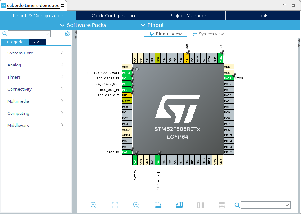
As you can see there is a push button (called B1) at pin PC13, an LED called LD2 at pin PA5, and a UART TX/RX at PA2/PA3 which connects to the programmer’s virtual COM port (if you’re unsure about this, do check out my earlier tutorial where I discuss it in some detail).
For now, this is all we will need. So, let us head over to the code window.
Navigate using the project explorer on the left to main.c.
The Basics: Blink an LED using HAL_Delay()
Before we start playing with the timer peripherals themselves, let’s ground ourselves with the basics: initially we’re going to make that on-board LED blink. Then, we’ll have a play with the timers and see how they can be made to be useful.
Inside main.c, head to the while(1) inside main().
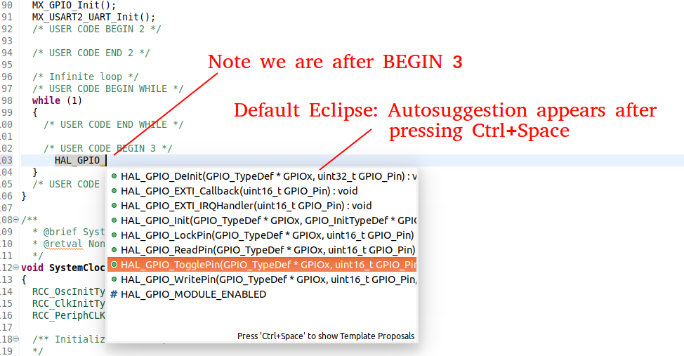
As a reminder, for these autogenerated files, you must only introduce code in the marked areas.
If you put code outside the USER CODE sections it will be deleted whenever the code generator runs (which is whenever we make a change to the hardware configuration).
For now, we’re going to add some code, as below. Remember you can get autocomplete suggestions by pressing Ctrl+Space at any time.
Add the following code:
In main.c, main():
  /* Infinite loop */
  /* USER CODE BEGIN WHILE */
  while (1)
  {
    /* USER CODE END WHILE */

    /* USER CODE BEGIN 3 */
	  HAL_GPIO_TogglePin(LD2_GPIO_Port, LD2_Pin);
	  HAL_Delay(1000);
  }
  /* USER CODE END 3 */
What does this do? Hopefully you’re able to work it out! In the infinite loop, it will first toggle the LED pin (changing it from high to low or vice versa) and then it will run the HAL_Delay() function.
HAL_Delay is what is known as a blocking function.
Inside the function is a loop which will iterate until the number of milliseconds that you specified as the argument elapses.
In other words, it will pause execution. In our case, we asked it to pause for 1000 milliseconds.
As such, when we compile and download this function to the board, the LED will blink.
The Basics: Our own custom delay function
One of the features of the HAL_Delay function is that it is based upon the SysTick of your STM32 microcontroller.
By default, this is an interrupt which triggers every one millisecond.
That doesn’t give us a tremendous amount of resolution (for instance, if we wanted to have a delay of 500 microseconds, that’s not possible by default).
Now, we know that the microcontroller architecture provides us a wealth of timer peripherals for us to use.
Let’s see if we can use one of these to make our own delay function which has a higher resolution than the default HAL_Delay().
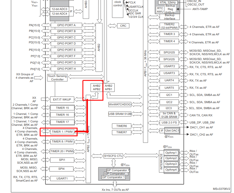
According to the ST General Purpose Timer Cookbook for STM32 Microcontrollers (an excellent resource which you can take a look at for further information), the first timer, TIM1, has an internal block diagram that looks like this:
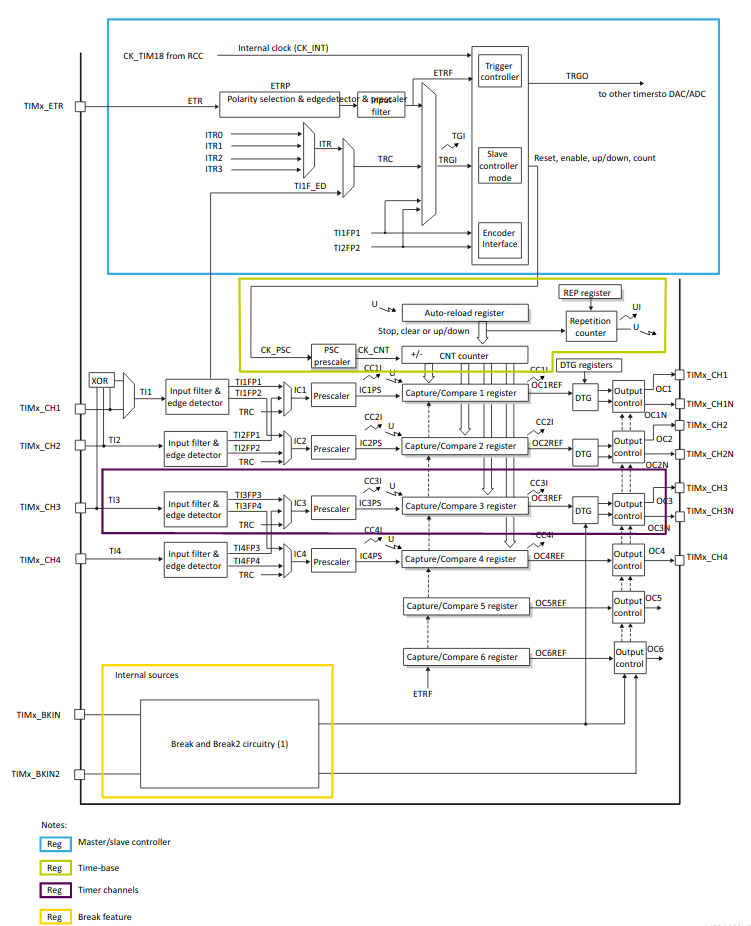
There’s quite a lot going on here! Fortunately, we want to just use one of the most simple modes. Let’s examine what we want to do: Firstly, we want to count time, not input events, so from the blue box we’ll be having the timer source based upon the clock ticks of the microcontroller. Secondly, we will need to decide how quickly we count based on that clock source, i.e. should we count the clock ticks directly, or should we divide them by some value? This decision is represented by the prescaler value (depicted by the PSC prescaler block in the green Time-base box). Finally, the actual “count” of the timer is stored in the register CNT, before further decision-making hardware uses this value in other ways (we’ll get to these later).
Let’s walk through an example. Let us decide that we wish to have TIM1 count in microseconds. Now we need to know how fast the TIM1 input clock is. In the Device Configuration Tool, we can see what this is under the Clock Configuration panel:
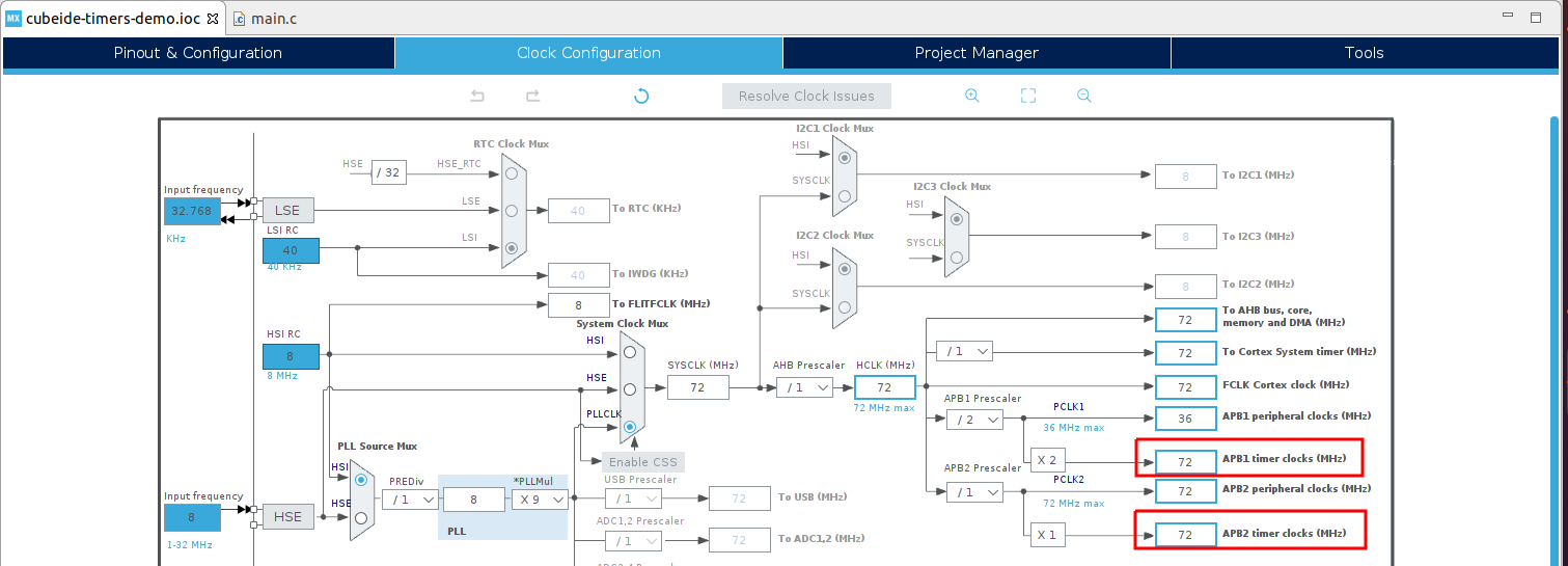
Aha! Now, while the two speeds are the same for APB1 timer clocks and APB2 timer clocks, if they were different, how would we know which source TIM1 depended upon?
The STM32F303RE datasheet can rescue us here:
So TIM1 actually comes from APB2 timer clock source.
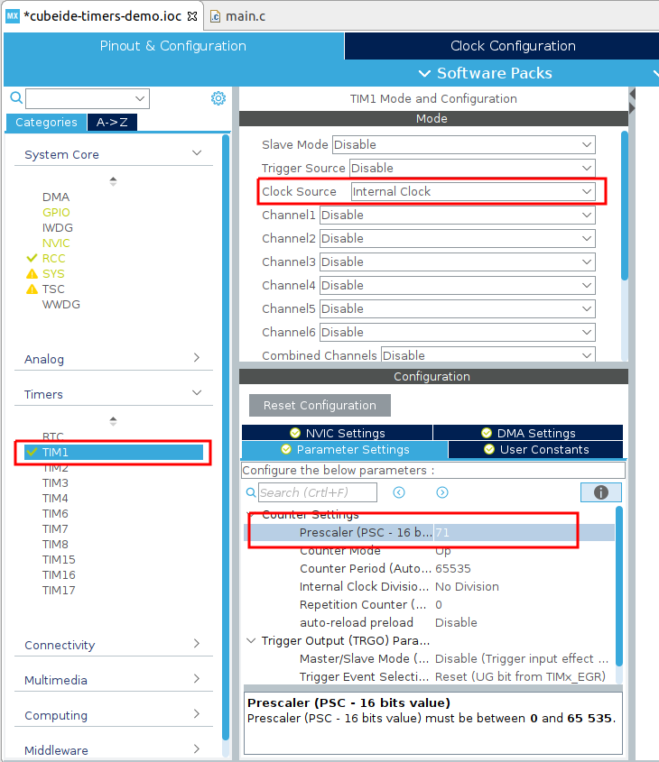
Now that we know that in our configuration TIM1 has a 72MHz source, we can start setting up the device. If we want a 1 microsecond resolution, we know that we’ll need to divide the clock by 72, as 72 MHz / 72 = 1 MHz, and 1 / 1 MHz = 1 microsecond. There’s one other note you must remember, which is that the prescaler is always stored as 1 less than the division. That is, a prescaler of 0 would divide the clock by 1 (i.e. it would not divide it). For our desired division, 72, we must therefore set the prescaler as 71.
Head back into the device configuration tool, and expand the settings for TIM1. Set the Clock Source to Internal Clock, and the Prescaler to 71, as depicted.
Now, save your configuration and press yes to regenerate code when prompted.
You should notice that an extra line of configuration has appeared in your main.c:
In main.c, main():
/* Initialize all configured peripherals */
  MX_GPIO_Init();
  MX_USART2_UART_Init();
  MX_TIM1_Init();
Great! Let’s now add our own little custom function:
In main.c private user code section:
/* Private user code ---------------------------------------------------------*/
/* USER CODE BEGIN 0 */
void delay_us (uint16_t us) //warning: this function is not reentrant
{
	__HAL_TIM_SET_COUNTER(&htim1,0); //reset the timer counter
	HAL_TIM_Base_Start(&htim1); //start the timer
	while (__HAL_TIM_GET_COUNTER(&htim1) < us);  // wait for the counter to reach the us value provided as an argument
	HAL_TIM_Base_Stop(&htim1); //stop the timer.
}
/* USER CODE END 0 */
Let’s walk through this piece of code.
We take in as an argument us the amount of time to wait in microseconds. Note that our argument is a 16-bit type. This is because TIM1’s register CNT is only 16 bits wide. That means it can only count up to 2^16-1, or 65535.
The first line of the function body resets the counter at the core of TIM1 by setting the CNT register (see the block diagram) to zero. The second line then starts the timer. The third line waits until the CNT register is greater than the argument we provided. This works because we know that CNT register will advance by 1 every 1 microsecond. Finally, the fourth line stops the timer.
There’s one thing to note with this function’s implementation: it is not reentrant. What does this mean?
Because the function has side effects (it resets/starts/stops the timer) when it is called, if this function was to be used in parallel the two function calls would interfere with one another. It is possible to write a version of this function such that it is reentrant (like HAL_Delay()), but let’s keep it simple and not worry about that for now.
Let’s try out our new functionality by modifying our while(1) in main.c to use the new delay function. Note that, as we discussed, we can’t request a delay greater than 65,535 microseconds. I choose to use 50,000:
In main.c, main():
/* USER CODE BEGIN WHILE */
  while (1)
  {
    /* USER CODE END WHILE */

    /* USER CODE BEGIN 3 */
		HAL_GPIO_TogglePin(LD2_GPIO_Port, LD2_Pin);
		delay_us(50000);
  }
  /* USER CODE END 3 */
If we compile and run this we should see that the LED is now blinking much more rapidly.
A timer interrupt
How can we avoid having blocking functions? The answer is to change our way of thinking. Rather than continuously checking to see if some request has finished (i.e. checking to see if the time delay has elapsed), we instead should request that the underlying archicture does the job and then informs us when it is complete. In computing terms this is known as an interrupt.
There are lots of ways to visualise interrupts, but the way that I like the most is to consider a common smoke detector. It works in parallel to you at home, and should a fire require your attention, it will interrupt whatever you’re doing by raising the alarm. Once you’ve dealt with the cause of the issue, you can return to your home life.
In the timer block diagram the interrupt hardware is managed by the capture/compare registers and represented by the signals CCxI. They have a few different operating modes, but in their simplest form you can consider them as “a value that the timer counts to”.
When we configure them, we can set them up such that upon the timer reaching some value, it calls a function in our C program - which we term the Interrupt Service Routine, or ISR.
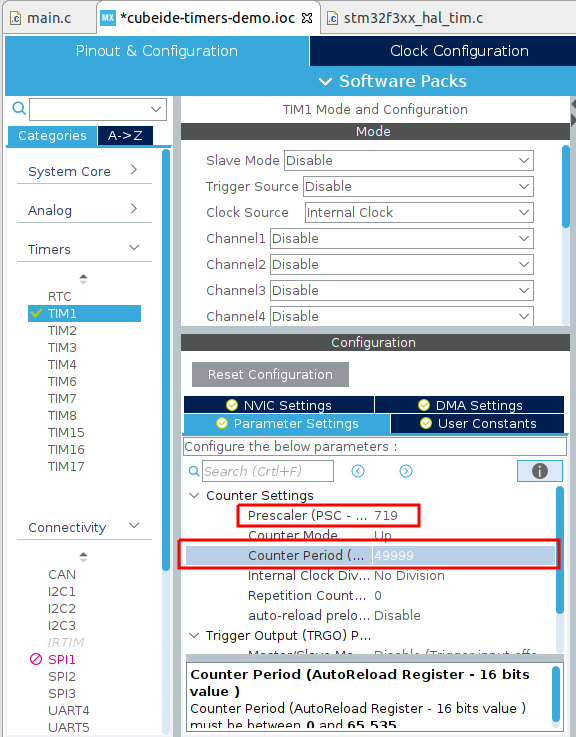
Let’s try an example. Let’s have our timer trigger an interrupt every 500 milliseconds. Head back into the device configuration tool, and then back into the TIM1 configuration. We’ll need to change our Prescaler PSC from 71 (i.e. divide clock by 72) to 719 (i.e. divide clock by 720, each tick representing 10 us). Then, we’ll change the counter period to 49999 - which means an overall period of 50,000 cycles (like the prescaler, this number is 1 less than the executed value).
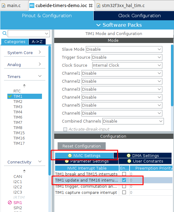
Now we need to enable the interrupt hardware. Select the NVIC settings tab, and then check the box for TIM1 update (note that this shares a TIM16 interrupt, but as TIM16 isn’t enabled this doesn’t bother us).
Now we need to add some code to use this interrupt. Head back to main.c.
Let’s first write the ISR for the timer period elapsed:
In main.c, private user code section:
/* Private user code ---------------------------------------------------------*/
/* USER CODE BEGIN 0 */
void delay_us (uint16_t us) //warning: this function is not reentrant
{ . . . }

void HAL_TIM_PeriodElapsedCallback(TIM_HandleTypeDef *htim) {
	HAL_GPIO_TogglePin(LD2_GPIO_Port, LD2_Pin);
}
/* USER CODE END 0 */
Now we need to actually use the timer (and remove the blinking LED code from earlier).
In main.c, main():
/* Initialize all configured peripherals */
  MX_GPIO_Init();
  MX_USART2_UART_Init();
  MX_TIM1_Init();
  /* USER CODE BEGIN 2 */
  HAL_TIM_Base_Start_IT(&htim1); //start the timer
  /* USER CODE END 2 */

  /* Infinite loop */
  /* USER CODE BEGIN WHILE */
  while (1)
  {
    /* USER CODE END WHILE */

    /* USER CODE BEGIN 3 */
	  // nothing to do in here at the moment . . .
  }
  /* USER CODE END 3 */
Note that we have to actually start the timer in interrupt mode ourselves, and don’t forget to delete the earlier code from USER CODE section 3.
Try out the execution now - what’s changed? Well, the LED should now be reliably blinking with a period of 1 second (that is, 500ms on, 500 ms off).
We’ve now succeeded in making this time-driven application using interrupts. This means we could put other code into our main while loop and not have to be waiting all the time for delays to finish! Within microcontrollers, interrupts are a key step on the journey to multi-tasking implementations and microcontrollers doing multiple control tasks at once.
Introduction to Pulse Width Modulation (PWM)
As it turns out, using a timer to turn on and off a pin at a regular interval (i.e. as a square wave) is an extremely common job requirement. This is because we can use square wave signals with varying duty cycles (i.e. varying ratios of on-off time) to change the effective amount of power that a given signal is transmitting. This is called Pulse Width Modulation, and Wikipedia has got some lovely details on it.
We can distill the important part into this picture:
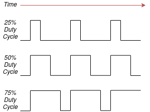
By varying the ratio of high time to low time while preserving the period of the signal (and while preserving the voltage and other characteristics) we are able to change the amount of transmitted power.
Let’s see an example. We’re going to need to change the configuration again, so head back into the device configuration tool.
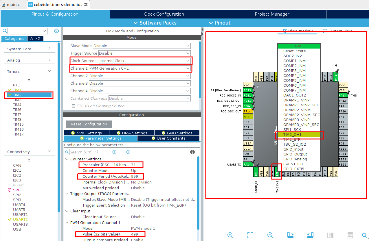
We’re going to drive the on-board LED using PWM, so we’ll need to change the setup for that pin. In the device configuration tool, set TIM1 to have prescaler zero again, and maximum period (65535). Then, set PA5 to be TIM2_CH1, which is a PWM source. Select TIM2 under Timers, enable it by setting the Clock Source to Internal Clock, and then set Channel 1 to PWM Generation CH1. Choosing the period of a PWM signal is largely dependent upon the application you’re using. For what we’ll be doing, 1kHz is a good value, so we’ll set the prescaler again to 71 (giving us 1 microsecond resolution) and then choose a counter period of 999 (that’s 1,000 microseconds or 1 millisecond = 1 kHz). We’ll then set an initial duty cycle of 50% by setting pulse to 499 (half of 1,000 - 1).
Depicted:
Save and regenerate your code. Now we need to edit our code again. Firstly, we want to use the TIM1 interrupt to change the duty cycle of TIM2. This will enable us to visualise the effects of a duty cycle that varies over time.
In main.c, private user code section:
/* Private user code ---------------------------------------------------------*/
/* USER CODE BEGIN 0 */
void delay_us (uint16_t us) //warning: this function is not reentrant
{ . . . }

void HAL_TIM_PeriodElapsedCallback(TIM_HandleTypeDef *htim) {
	//change the duty cycle of TIM2 whenever the TIM1 interrupt occurs.
	static uint8_t dir = 0; //direction: are we currently increasing duty cycle or currently decreasing?
	uint32_t i = __HAL_TIM_GET_COMPARE(&htim2, TIM_CHANNEL_1); //the period is 1000. Duty cycle should vary between 0 and 1000.

	if(dir == 0) { //change duty cycle by changing "i" by 1 in the positive or negative direction
		i--;
		if(i == 0) {
			dir = 1;
		}
	} else {
		i++;
		if(i == 1000) {
			dir = 0;
		}

	}
	//update the PWM control register
	__HAL_TIM_SET_COMPARE(&htim2, TIM_CHANNEL_1, i);
}
/* USER CODE END 0 */
There’s quite a lot going on in there, but hopefully the comments can walk you through it. Essentially, we are varying the register which controls the duty cycle of the PWM signal by changing it from 0 (representing 0% duty cycle) to 1000 (representing 100%). As this has been encoded as the TIM1 ISR, this will happen each time that TIM1 reaches the end of its period.
Now we need to enable the PWM output.
In main.c, main():
/* Initialize all configured peripherals */
  MX_GPIO_Init();
  MX_USART2_UART_Init();
  MX_TIM2_Init();
  MX_TIM1_Init();
  /* USER CODE BEGIN 2 */
  HAL_TIM_Base_Start_IT(&htim1);
  HAL_TIM_PWM_Start(&htim2,TIM_CHANNEL_1); //enable PWM output on LED pin
  /* USER CODE END 2 */

  /* Infinite loop */
  /* USER CODE BEGIN WHILE */
  while (1)
  {
    /* USER CODE END WHILE */

    /* USER CODE BEGIN 3 */
	  // nothing to do in here at the moment . . .
  }
  /* USER CODE END 3 */
Compile and download this to the board, and this is what you should see:
Compare that to earlier - this LED is now fading on and off as the PWM duty cycle goes from 0% to 100%.
A silly application: PWM to generate AM radio transmission
Electrical signals like PWM tend to radiate electromagnetic radiation. This is usually not what we want, but for the rest of this tutorial, we’ll actually (ab)use this property to generate an AM radio transmission!
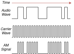
Let’s first take a brief look at what AM radio is. AM stands for Amplitude Modulation. This means we take a carrier wave and combine it with some information signal, by changing the amplification of the carrier wave over time.
As always, Wikipedia has a great explanation, and this figure (CC BY-SA 3.0) by Ivan Akira has an outstanding visualisation of how the combination of the signals works in practice:
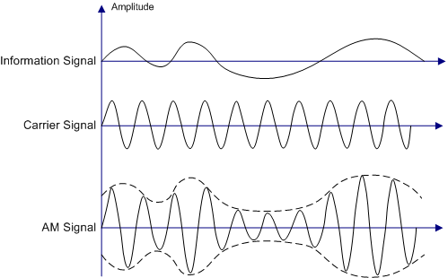
For an AM audio transmission, the information signal represents the audio we want to transmit, and the carrier wave is the frequency you would tune your radio to.
Through careful use of the PWM abilities of our microcontroller, we can generate a complete AM radio signal using just software.
Note: Depending on the laws of your country, generating and emitting unlicensed radio wave signals (even the extremely weak ones that we’ll be working with here) may get you in trouble. Proceed at your own risk.
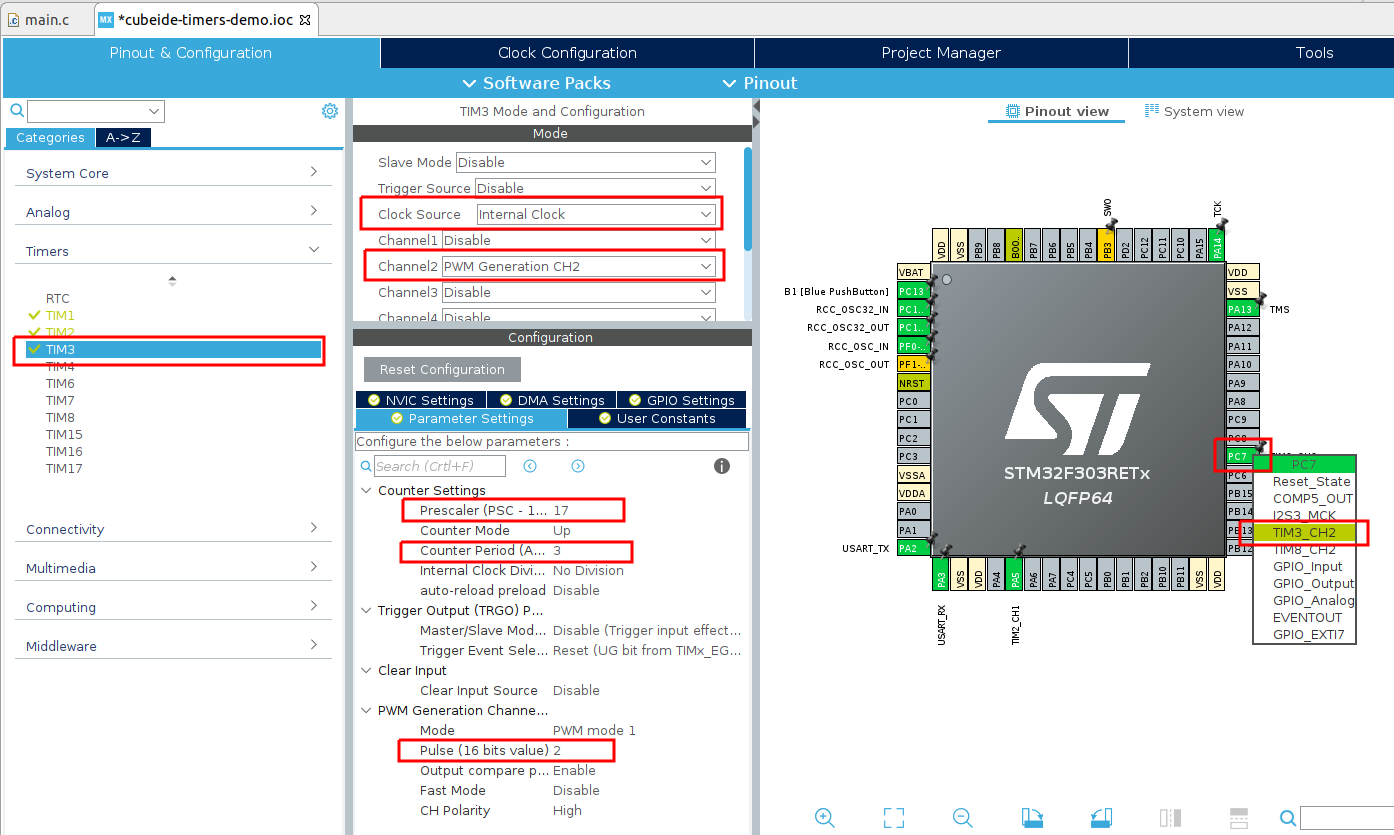
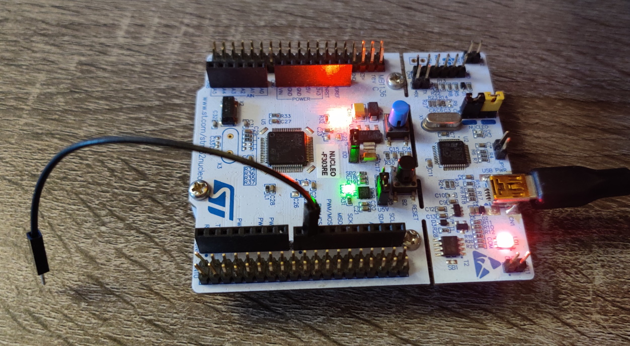
The first trick is to generate the carrier wave itself, so let’s do that now. I want my frequency to be at 1,000 kHz as this is a fairly normal frequency for AM radio, and I’ll need to choose a pin to use as an Antenna. I’ve selected the pin labelled PWM/D9 on the Arduino headers. If we look at the schematic for the board, we can see that this pin goes to PC7 on the processor, which has the option to become PWM channel TIM3_CH2.
Let’s do some quick math. If we divide the clock by 18 then the clock is at 4MHz. If we then set the clock period as 4 then we have an overall period of 1MHz (or 1,000 kHz). To get a good carrier wave the duty cycle should be 50%, so we set the Pulse to 2.
Depicted:
Now let us enable the signal. Regenerate the code and head into main.c again:
In main.c, main():
/* Initialize all configured peripherals */
  MX_GPIO_Init();
  MX_USART2_UART_Init();
  MX_TIM2_Init();
  MX_TIM1_Init();
  /* USER CODE BEGIN 2 */
  HAL_TIM_Base_Start_IT(&htim1);
  HAL_TIM_PWM_Start(&htim2,TIM_CHANNEL_1); //enable PWM output on LED pin
  HAL_TIM_PWM_Start(&htim3,TIM_CHANNEL_2);
  /* USER CODE END 2 */

  /* Infinite loop */
  /* USER CODE BEGIN WHILE */
  while (1)
  {
    /* USER CODE END WHILE */

    /* USER CODE BEGIN 3 */
	  // nothing to do in here at the moment . . .
  }
  /* USER CODE END 3 */
Download this to your board now, and plug a loose wire into the Arduino header pin PWM/D9. Tune a radio to 1kHz AM, and then press the reset buton on your board. You should be able to hear the carrier wave come in and out.
Demo:
Of course, this is not tremendously interesting. What we’d like to do is overlay an audio signal on top of this wave. Guess what - we can do that (in a sense). Recall that audio waves can themselves be represented in a rectangular fashion, and that AM says we change the amplification of our signal.
Well, while we don’t have fine-grain control over the voltage of our PWM, we do have the ability to turn it on and off, which gives us two levels of amplification - 0% and 100%. So if our audio signal is also only made up of rectangular waves, we can combine them, like so:
So how can we generate these audio waves? Well, audio itself can be represented as square waves of varying frequencies. For instance, the note A4 is 440Hz, B4 is 493.88Hz, and so on.
Let’s try make a single tone come through our AM radio - A4. This means we’ll need to turn the PWM channel on and off 440 times a second.
To do this I’m going to rejig our microsecond delay function delay_us from earlier (as we retasked TIM1 to the fading LED job).
So, let’s introduce another timer, TIM4, and set it up with a prescaler of 71, just as we did earlier.
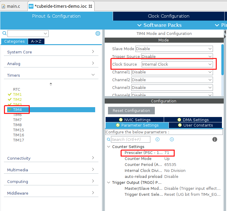
Regenerate your code, and update the delay_us function to now use htim4 instead of htim1.
We’re also going to leave the timer running always, rather than starting and stopping it (this will make the function slightly more accurate as it won’t have as many extraneous instructions).
In main.c, private user code section:
/* Private user code ---------------------------------------------------------*/
/* USER CODE BEGIN 0 */
void delay_us (uint16_t us) //warning: this function is not reentrant. NOTE CHANGE TO TIMER 4
{
    __HAL_TIM_SET_COUNTER(&htim4,0); //reset the timer counter
	while (__HAL_TIM_GET_COUNTER(&htim4) < us);  // wait for the counter to reach the us value provided as an argument
}

void HAL_TIM_PeriodElapsedCallback(TIM_HandleTypeDef *htim) {
	. . .
}
/* USER CODE END 0 */
And now update our main to toggle the PWM on and off at an appropriate speed:
In main.c, main():
/* Initialize all configured peripherals */
  MX_GPIO_Init();
  MX_USART2_UART_Init();
  MX_TIM2_Init();
  MX_TIM1_Init();
  MX_TIM3_Init();
  MX_TIM4_Init();
  /* USER CODE BEGIN 2 */
  HAL_TIM_Base_Start_IT(&htim1);
  HAL_TIM_PWM_Start(&htim2,TIM_CHANNEL_1); //enable PWM output on LED pin
  HAL_TIM_Base_Start(&htim4);

  /* USER CODE END 2 */

  /* Infinite loop */
  /* USER CODE BEGIN WHILE */
  while (1)
  {
    /* USER CODE END WHILE */

    /* USER CODE BEGIN 3 */
	  delay_us(500000/440); //desired frequency is 440Hz, toggle at 220Hz. Delay is thus (1/f*1000000)/2 to get to us, or 500000/f.
	  HAL_TIM_PWM_Start(&htim3,TIM_CHANNEL_2);
	  delay_us(500000/440);
	  HAL_TIM_PWM_Stop(&htim3,TIM_CHANNEL_2);
  }
  /* USER CODE END 3 */
If you run and download this now, you will note that a tone at 440Hz is being generated through your radio! If you want an exercise for yourself, use the on-board button to turn the tone generator on and off and now you have a morse code transmitter!
Let’s play some music
Extending our single-tone radio to let us spin up a table of musical notes (so we can play a song) is not particularly difficult from this point!
Let’s step through some more modifications (remember that delay_us is still based on TIM4).
In main.c, private user code section:
/* Private user code ---------------------------------------------------------*/
/* USER CODE BEGIN 0 */
void delay_us (uint16_t us) //warning: this function is not reentrant
{
    . . .
}

void HAL_TIM_PeriodElapsedCallback(TIM_HandleTypeDef *htim) {
	. . .
}

//First we define our note frequencies and delays via a conversion function, an enum, and our look-up-table array.
#define FREQ_TO_DELAY_US(x) (500000 / x)
typedef enum {
	note_a 		= 0,
	note_a_sh 	= 1,
	note_b 		= 2,
	note_c 		= 3,
	note_c_sh 	= 4,
	note_d 		= 5,
	note_d_sh 	= 6,
	note_e 		= 7,
	note_f 		= 8,
	note_f_sh 	= 9,
	note_g		= 10,
	note_g_sh	= 11
} note_enum;

#define SCALE_LEN 12
uint16_t note_delays_us[] = {
	FREQ_TO_DELAY_US(220),
	FREQ_TO_DELAY_US(233),
	FREQ_TO_DELAY_US(247),
	FREQ_TO_DELAY_US(262),
	FREQ_TO_DELAY_US(277),
	FREQ_TO_DELAY_US(294),
	FREQ_TO_DELAY_US(311),
	FREQ_TO_DELAY_US(330),
	FREQ_TO_DELAY_US(349),
	FREQ_TO_DELAY_US(370),
	FREQ_TO_DELAY_US(392),
	FREQ_TO_DELAY_US(415),
	FREQ_TO_DELAY_US(440),
	FREQ_TO_DELAY_US(466),
	FREQ_TO_DELAY_US(494),
	FREQ_TO_DELAY_US(523),
	FREQ_TO_DELAY_US(554),
	FREQ_TO_DELAY_US(587),
	FREQ_TO_DELAY_US(622),
	FREQ_TO_DELAY_US(659),
	FREQ_TO_DELAY_US(698),
	FREQ_TO_DELAY_US(740),
	FREQ_TO_DELAY_US(784),
	FREQ_TO_DELAY_US(831)
};

//Now we define note durations {Quarter, Eighth, Sixteenth, Thirtysecond; Half; Whole}
#define NOTE_LEN_Q 652
#define NOTE_LEN_E (NOTE_LEN_Q/2)
#define NOTE_LEN_S (NOTE_LEN_Q/4)
#define NOTE_LEN_T (NOTE_LEN_Q/8)
#define NOTE_LEN_H (NOTE_LEN_Q*2)
#define NOTE_LEN_W (NOTE_LEN_Q*4)

//playNote struct provides the container to hold a given note in a song together
typedef struct {
	note_enum note;         //the note that is played
	uint8_t scale_pos;      //is it our upper scale or our lower scale (either 0 or 1)
	uint16_t duration_ms;   //for how long will the note be played?
	uint16_t duration_rest; //after the note, how long should we rest for?
} playNote;

//A song made up as the struct
playNote furEliseSong[] = {
	{note_e, 1, NOTE_LEN_E, 0},
	{note_d_sh, 1, NOTE_LEN_E, 0},
	{note_e, 1, NOTE_LEN_E, 0},
	{note_d_sh, 1, NOTE_LEN_E, 0},
	{note_e, 1, NOTE_LEN_E, 0},
	{note_b, 1, NOTE_LEN_E, 0},
	{note_d, 1, NOTE_LEN_E, 0},
	{note_c, 1, NOTE_LEN_E, 0},
	{note_a, 1, NOTE_LEN_Q, NOTE_LEN_E},

	{note_c, 0, NOTE_LEN_E, 0},
	{note_e, 0, NOTE_LEN_E, 0},
	{note_a, 1, NOTE_LEN_E, 0},
	{note_b, 1, NOTE_LEN_Q, NOTE_LEN_E},

	{note_e, 0, NOTE_LEN_E, 0},
	{note_g_sh, 0, NOTE_LEN_E, 0},
	{note_b, 1, NOTE_LEN_E, 0},
	{note_c, 1, NOTE_LEN_Q, NOTE_LEN_E},

	{note_e, 0, NOTE_LEN_E, 0},
	{note_e, 1, NOTE_LEN_E, 0},
	{note_d_sh, 1, NOTE_LEN_E, 0},
	{note_e, 1, NOTE_LEN_E, 0},
	{note_d_sh, 1, NOTE_LEN_E, 0},
	{note_e, 1, NOTE_LEN_E, 0},
	{note_b, 1, NOTE_LEN_E, 0},
	{note_d, 1, NOTE_LEN_E, 0},
	{note_c, 1, NOTE_LEN_E, 0},
	{note_a, 1, NOTE_LEN_Q, NOTE_LEN_E},

	{note_c, 0, NOTE_LEN_E, 0},
	{note_e, 0, NOTE_LEN_E, 0},
	{note_a, 1, NOTE_LEN_E, 0},
	{note_b, 1, NOTE_LEN_Q, NOTE_LEN_E},

	{note_e, 0, NOTE_LEN_E, 0},
	{note_c, 1, NOTE_LEN_E, 0},
	{note_b, 1, NOTE_LEN_E, 0},
	{note_a, 1, NOTE_LEN_Q, NOTE_LEN_Q}
};

//definitions finished, onto the functions to play the notes

//tx_tone takes a delay time and a play time, and will switch on and off the carrier PWM signal according to those arguments.
//this generates a tone in the PWM carrier in the AM frequency band.
void tx_tone(uint32_t dTime, uint32_t playTime) {
	uint32_t end = HAL_GetTick() + playTime;

  	while (end > HAL_GetTick()) {
	  	delay_us(dTime);
	  	HAL_TIM_PWM_Start(&htim3, TIM_CHANNEL_2);
	  	delay_us(dTime);
	  	HAL_TIM_PWM_Stop(&htim3, TIM_CHANNEL_2);
  	}
}

//tx_note takes a playNote structure and does the conversion into the arguments that tx_tone will take.
//firstly it transmits the note frequency (using the note_delay_us look up table) for 50 milliseconds less than requested,
//then it transmits "silence" for 50 milliseconds (this gives a gap between notes).
//Finally, if the playNote structure requests a further rest, it will extend the rest by that much amount of time.
void tx_note(playNote *n) {
	tx_tone(note_delays_us[n->note + SCALE_LEN * n->scale_pos], n->duration_ms-50);
	tx_tone(1, 50);
	if(n->duration_rest > 0) {
		tx_tone(1, n->duration_rest);
	}
}
/* USER CODE END 0 */
There’s a lot going on here, but rest assured none of it is complicated. Let’s briefly talk about the musical theory.
Firstly, as we discussed earlier, each note has a defined frequency (i.e. note A being 440 Hz). We showed in the previous example how we use the formula 500000/freq to convert it into a toggling delay for code that rapidly turns the PWM (carrier signal) on and off to generate the note at that tone.
So, our first job is to define some notes and their frequencies. I do this with a #define that contains the function to convert frequency to delay; a note_enum to hold the different note names, and a lookup table note_delays which has elements corresponding to the values in the enum.
As I want to have two scales of notes, the note_delays array is twice as long as the note_enum and I define the length of the scale to be 12.
Musical theory also says that notes have durations, i.e. for how long they are played. These all bear relation to one another. I define the Quarter note as the base (as it is the most common note) to be 652 milliseconds, meaning we’re playing at about 92 beats per minute.
I then define a structure playNote as a container to hold musical notes from a song.
They have every piece of information they need bundled together: the note enum, the scale position, and the duration.
I also add as an element to the struct duration_rest, which can be used to add a musical rest after the note has finished.
We then move onto two functions.
The first, tx_tone, works as our earlier example did and simply switches the PWM carrier signal on and off rapidly according to the note frequency delay.
The second, tx_note, takes a pointer to a playNote structure and does the translation into the format/arguments that tx_tone requires.
And in the main loop,
In main.c, main():
/* Initialize all configured peripherals */
  MX_GPIO_Init();
  MX_USART2_UART_Init();
  MX_TIM2_Init();
  MX_TIM1_Init();
  MX_TIM3_Init();
  MX_TIM4_Init();
  /* USER CODE BEGIN 2 */
  HAL_TIM_Base_Start_IT(&htim1);
  HAL_TIM_PWM_Start(&htim2,TIM_CHANNEL_1); //enable PWM output on LED pin
  HAL_TIM_Base_Start(&htim4);

  /* USER CODE END 2 */

  /* Infinite loop */
  /* USER CODE BEGIN WHILE */
  while (1)
  {
    /* USER CODE END WHILE */

    /* USER CODE BEGIN 3 */
	  for(int i = 0; i < 35; i++) { //35 notes to send
		  tx_note(&furEliseSong[i]);
	  }
  }
  /* USER CODE END 3 */
That’s it, we’re good to go. Compile and run, and you should hear the first few bars of Fur Elise through your radio! I took a recording using my RTL-SDR to demonstrate:
That brings us to the end of this tutorial. Feel free to chop and change the provided code as necessary - see what other functionality and/or songs you can produce!
Conclusions
In this tutorial we looked at timers, timer interrupts, and PWM. We made two combined applications: a fading LED, and an AM radio transmitter.
If you would like the complete code that accompanies this blog post, it is made available in the associated Github repository here.